Continue to Site

Eng-Tips is the largest engineering community on the Internet

Intelligent Work Forums for Engineering Professionals

  • Congratulations KootK on being selected by the Eng-Tips community for having the most helpful posts in the forums last week. Way to Go!

Setback from bridge abutment to creek bank 2

Status
Not open for further replies.

ckissick

Geotechnical
Jul 12, 2006
26
There is a 10-foot deep, shotcrete lined creek with a pedestrian bridge being built over it. The banks are inclined at 1/2 to 1. The ground away from the banks is level. The bridge will use concrete abutments, 3 feet wide by 10 feet long, by 5 feet deep. The abutments will be about 10 feet away from the tops of the creek banks. The soil is stiff to very stiff (N=14 to 19 at a depth of 10 feet)lean clean in 4 borings. No groundwater.

The structural engineer wants to know the passive resistance provided by the wedge of soil between the abutment and the creek bank so he can decide if tiebacks are needed to hold the abutment back, especially in the event of an earthquake. The site is near the San Andreas fault. I know a rule of thumb is 7 to 9 feet from a slope, and the Ca Building code recommends a 45 degree angle from the bottom of the creek bank to preserve bearing capacity. But what about passive resistance? Without the creek bank, I would say 300 PCF. I'm thinking it would not be much less with the bank being 10 feet away. Is there a chart or method I am not aware of? Does Schmertmann have a method?
 
Replies continue below

Recommended for you

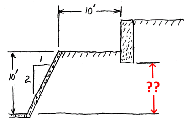
Is this (terraced "retaining walls") what you are evaluating?

If so, the lower "retaining wall" (concrete lined bank) was likely not designed for surcharge load from an upper wall. Bottom of the abutment footing should be no more than 5' (half the 10' horizontal distance between the "walls") above the creek invert to prevent surcharge loading on the creek bank "wall". If separation is not adequate... make it so.

When the two "walls" have proper separation, the two "walls" can be considered independent. Passive resistance of the abutment can be calculated as if the lower "wall" does not exist.

Terraced_Retaining_Walls-600_csvipe.png
 
The ground beyond the creek banks is at one elevation, not two elevations, as you drew it. The abutments are buried on both sides, not retaining anything. The structural engineer is concerned that the soil between the abutments and the creek banks won't provide passive resistance because of the creek. I think it will provide passive resistance. The question is, how much will it be reduced? I know a rule of thumb by some is you need a distance 7 to 10 feet to preserve full passive. But I would like to find something that can verify or modify this assumption.
 
ckissick said:
The ground beyond the creek banks is at one elevation... the abutments are buried on both sides, not retaining anything.

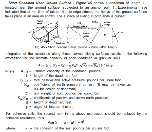
In that case, I consider the abutment analogous to a short, shallow deadman anchor for a sheet pile wall. The creek shotcrete lining represents the "sheet piling" (good enough) and the horizontal seismic force on the abutment is substituted for "tie rod tension".

See the "US Steel Sheet Piling Design Manual", beginning on page 44. Here is a relevant excerpt:

Abutment_Passive_Pressure-600_v0bacs.png
 
You can draw the passive failure wedge using either Rankin's or Coulomb's theory. The line should be drawn from the toe of the embankment towards the channel. If the channel is completely out of the failure wedge, you can provide the passive pressure with a safety factor (2-4) to the structural engineer. If the line intercepts the channel, you need to perform the wedge analysis to evaluate the available passive pressure.
 
ckissick said:
The structural engineer wants to know the passive resistance provided by the wedge of soil between the abutment and the creek bank so he can decide if tiebacks are needed to hold the abutment back, especially in the event of an earthquake.

During an earthquake, both the abutment and the shotcrete creek bank lining will be subjected to seismic force. Both could potentially fail at the same time. This is the reason for my sheet pile / deadman analogy. I've seen something similar (retaining wall falls over & drags deadmen with it). This incedent was not caused by an earthquake, but by excessive surcharge loading and over-dredging in front of a waterfront retaining wall.

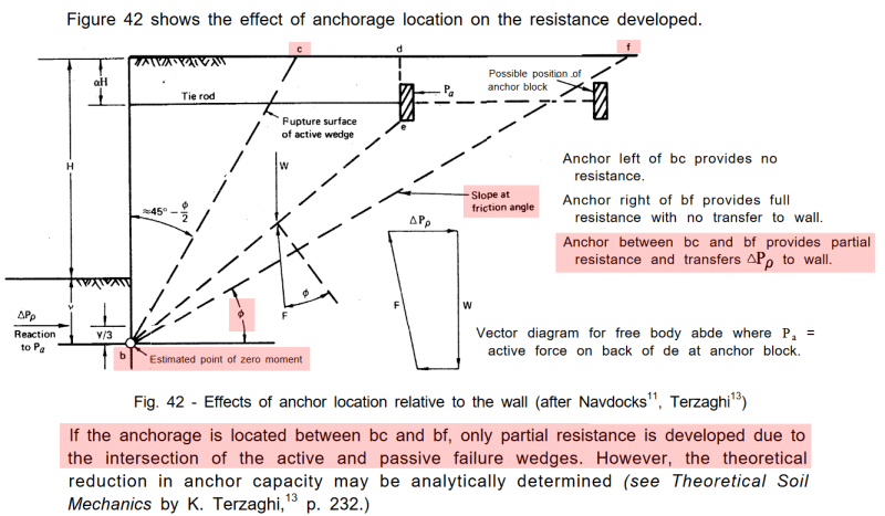
The abutment (deadman analogy) needs to be located as shown in the referenced Design Manual, i.e. beyond the friction angle slope to obtain full benefit of passive pressure resistance:

Anchor_Failure-1-600_zlqnot.png


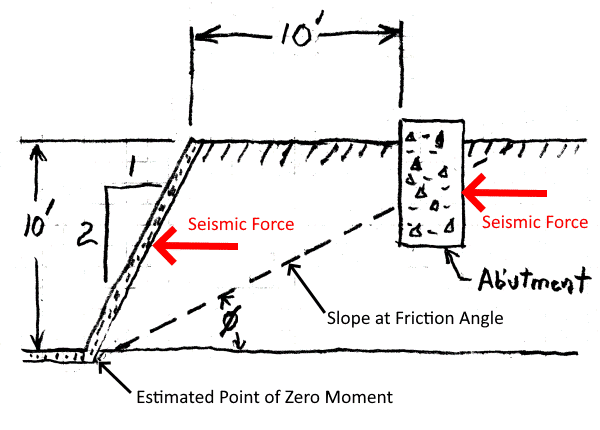
This is my (approximately to scale sketch) adaptation of the sheet pile / deadman analogy to the OP's question:

Abutment-600_eugv0d.png


Appears there is a good chance the abutment is not far enough away from the shotcrete lining to allow full passive resistance.
 
Status
Not open for further replies.

Part and Inventory Search

Sponsor