Continue to Site

Eng-Tips is the largest engineering community on the Internet

Intelligent Work Forums for Engineering Professionals

  • Congratulations KootK on being selected by the Eng-Tips community for having the most helpful posts in the forums last week. Way to Go!

Settlement of Pipes

Status
Not open for further replies.

geotechguy1

Civil/Environmental
Oct 23, 2009
667
Anyone have any good references on settlement of rigid and flexible pipes. I've only been able to find references that relate to settlement of the fill over the pipe rather than settlement of the pipe itself. I have buried pipe design by Moser and other similar references but haven't found anything of use. Especially interested in soft ground conditions
 
Replies continue below

Recommended for you

What do you mean by "references"?

This is simply part of design.

In general pipes are laid on native undisturbed ground and impose only a small surcharge on the soil compared to the normal backfill.

I've had to do some special stress analysis on really soft soils such as peat bogs but they are unusual.

Only when you get extra surcharge on the soil and the ground under the pipe compresses due to this extra load, e.g. Building an embankment for a road does the soil under the pipe settle or compress.

A bit more context would help.

Remember - More details = better answers
Also: If you get a response it's polite to respond to it.
 
Reference manuals, research papers, case studies and the like; sorry I wasn't clear. The book I have is buried pipe design by moser, 3rd edition.

I'm working with pipes installed in peat - note that this is not fibrous peat or a 'bog' as the case may be in north america but essentially amorphous peat with undrained shear strengths of 25-50 kpa. Settlements of 2" are occuring in the pipes shortly after backfilling. We have a pretty beefy gravel raft with geogrid and cloth under the pipes.

We've been thinking about possible causes and the ideas so far are:

[ul]
[li]Backfill is being placed to a higher density than in-situ increasing stress[/li]
[li]The gravel used for the raft under the pipe is significantly heavier than the peat (doesn't seem to be the case because the peat isn't fibrous) [/li]
[li]The pipe is concrete and thus significantly stiffer than the sidefill / embedment material and thus picks up more of the load from the backfill and concentrates it under the pipe - the point of the raft is to spread the load back out to mitigate this issue and provide a working surface but perhaps we haven't specified a thick enough raft[li]
[li]The project is fairly unique in it's structure and contract for the area so it's possible that his is a human / contracting factor: That is, we've screwed up the way the sub contractors normally underbid jobs by including the gravel raft in the contract when normally they seem to not plan for it and then have an extra / change request for undercutting the trench bases - and now the contractor is desperately trying to fabricate the need for a change request.[/li]
[li]The subgrade is sensitive and groundwater shallow and the vibration from compaction of the raft is enough to weaken the subgrade and draw water up - I've had this happen before in earthworks not involving pipes and we generally solved this by bridging the weak layer with a thick lift of non compacted granular fill[/li]
[/ul]

For solutions, using fillcrete instead of gravel, increasing the thickness of the gravel layer up to a meter or so. I've also thought about asking the designer to switch away from concrete to a flexible pipe and alter the design to increase the grade. I think a flexible pipe with good side support would behave more like a fully compensated foundation (i.e. the stress distribution isn't changed as much whereas the concrete pipe is concentrating the load from the backfill and also susceptible to differential settlements). I don't quite understand why they chose concrete for this application because the risk of total and differential settlement should have been obvious or, at the very least, if they had bothered to ask me I would have told them. Note that I'm not the pipe designer and this is the usual situation where the civil engineer completely ignored anything to do with geotech until things started failing and now wants to blame everything on the geotech he never consulted.

 
Overall pipes are laid on local undisturbed ground and force just a little additional charge on the soil contrasted with the ordinary inlay.

I've needed to do some exceptional pressure examination on truly delicate soils, for example, peat lowlands yet they are strange.

Just when you get additional charge on the soil and the ground under the pipe packs because of this additional heap, for example Building a bank for a street does the soil under the pipe settle or pack.

Devon Wyatt , Construction Manager
 
Hi geotechguy1 (Civil/Environmental)(OP),

I agree with your second post.. In order to get better responds, pls provide some information ( GWL, depth of peat, the type and diameter of pipe typical trench depth and backfill properties etc..)

Regarding the settlement of flexible pipes , i will suggest you to look ;

- BS EN 1993-4-3,Design of steel structures - Part 4-3: Pipelines

- PIPELINE DESIGN and CONSTRUCTION , A Practical Approach by MOHITPOUR

- Buried Flexible Steel Pipe Design and Analysis (ASCE Manual No. 119 )

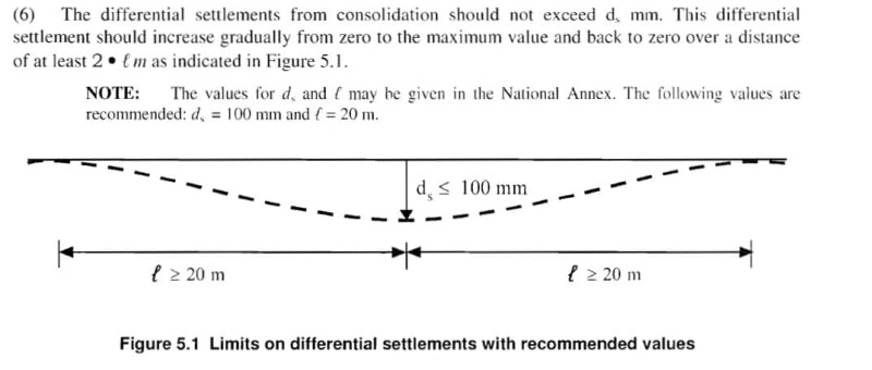
The following excerpt from BS EN 1993-4-3:

differential_settlement_of_pipes_xtdb3l.jpg


In case of rigid pipes, the joints should have some flexibility ( socket spigot with rubber gasket etc .) and short pieces should be provided at connections to structure ( manhole etc)..
 
Pipelines should not be placed in soil where settlement will cause overstress, nor pulling apart of joints. Unsuitable material should be removed and replaced with materials that provide support, compact granular fill, etc.

In areas where this cannot be accomplished, screw anchors may provide a solution. Screw anchors with extension rods and support brackets can even be adapted to setting and holding a given pipe elevation in both poor soils and can even work as a support structure for spanning pipe located in water, pipe spanning between supports at elevations above the mud line.
 
We've done the remove and replace with gravel thing although the thickness is limited; have thought about making it thicker though. I guess the steel bracket would just be a strap over top and you'd attach it at both sides to small screw piles or anchors? I've also thought of just putting the thing on pipeline cradles
 
Or large screw anchors. Just keep adding rod extensions until the shear pins pop. I've used cross bracing between rod extensions to provide lateral strength for a water crossing, like I described above. Yes, just use one clamp above and one below the pipe. I have also used screw anchors for swamp crossings and peat boggs in "The Land of 10,000 Lakes" and in Lousiana swampland, going through the bayou, land/swamp/tidal flats, too thick to drink and too thin to plow stuff, on up to 36" diameter pipelines. They can be very useful. I wouldn't try using cradles. Screw anchors will be easier and won't nove on you later.

You can try getting a neutral buoyancy by varying weight coating and pipe wall thickness, but results are not nearly so well guaranteed as screw anchors. I do not work for a screw anchor company, but obviously I am a fan.
 
I've designed a few pipelines in peat and if you find anything that is worthwhile please let me know. Basically there is very little reliable useful information out there.

Peat is a very soft, highly variable material which has very limited bearing capacity and also tends to creep and have long term settlement under very low bearing pressures.

In then end it boils down to three options

1) Avoid the peat field. Seriously, unless there is no other option, peat is a truly horrible material.

2) Try and reinforce an area of peat probably 2-3 times the diameter of the pipe. To avoid just adding more weight, try and do this with neutrally buoyant material such as rigid plastic mesh or bamboo sticks or willow matting. That gravel you're using is, IMHO, not a good idea as it is much heavier than the peat and hence will just add to the loading on it and will also end up acting like a land drain. Any sort of slope, even 1 degree and you'll end up trying to drain the bog - not a good plan.

The Victorians worked it out - see crossing Chat Moss with the Liverpool to Manchester railway. They laid down timber in a herring bone fashion, added heather, branches and other similar material and then built their embankment for the railway. Still there to this day.

But if you're going to build a floating road type pipeline then it needs to be flexible. Rigid concrete pipes are a bad idea.

I've stood on a long straight road laid on peat and when a heavy lorry came along you could actually see the rolling wave in front of it. The tarmac was covered with lines at 90 degrees showing the flexing of the road.

3) Dig out the peat all the way to something solid and fill it back with stone. You probably need to fit water traps / plugs with clay every 50-100m to stop this becoming a giant drain. It's basically he only way you can actually guarantee to a reasonable degree that you won't get any settlement. But then you need to find somewhere to dump all your peat....

Remember - More details = better answers
Also: If you get a response it's polite to respond to it.
 
Status
Not open for further replies.

Part and Inventory Search

Sponsor