Eng-Tips is the largest engineering community on the Internet

Intelligent Work Forums for Engineering Professionals

  • Congratulations waross on being selected by the Tek-Tips community for having the most helpful posts in the forums last week. Way to Go!

shaft cover calculation

Status
Not open for further replies.

mech_eng_p

Industrial
Mar 9, 2018
10
0
0
NL
Hi.
I am trying to calculate a flat shaft cover, mounted with several bolts.
These are the dimensions (in metric system):
shaftØ140mm
cover outer D=160mm
thickness=12mm
bolt= M16 (3x), hole Ø18mm, pretension bolts is 640*70%MPa.
PCD=Ø110mm

First I tried doing this with the use of Roark formulas for stress and strain (Chapter 11, case 9a).
The results was a bendingstress at the centre of the plate of about 395 MPa.

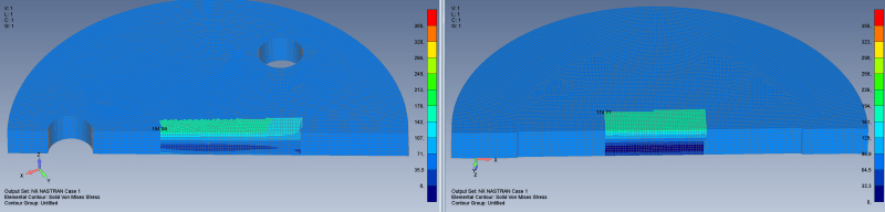
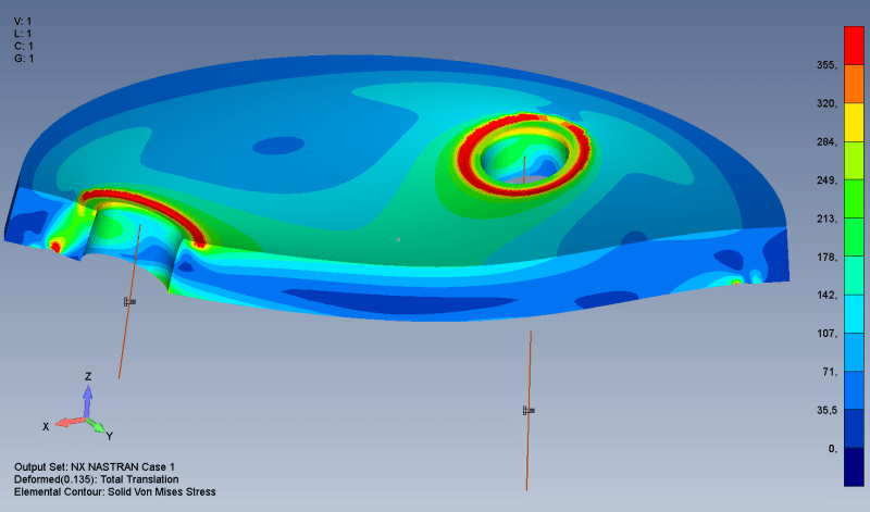
For some reason, i wasn't expecting this high stresses, so i did a FEM analysis.

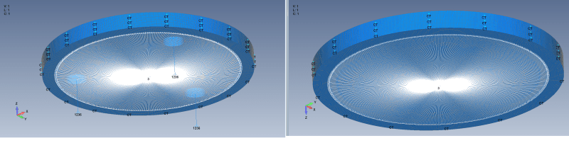
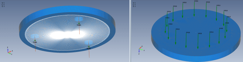
Pivot support, 3x 70300N (pre)tension.
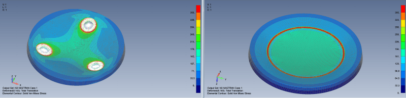
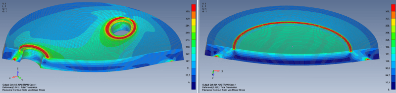
With the following results: Maximum stress at centre plate about 150MPa.
shaft_cover_e10grq.png


This is indeed a huge difference.

I was assuming that using the uniform load of roark was a good idea, but maybe it was not.
Unfortunately i haven't found any other useful calculation to calculate the stress in a shaft cover (with holes).

Can anybody help me finding this?


Thanks!
 
Replies continue below

Recommended for you

Well, the case from Roark's that you've mentioned is a simply supported (at the edge) homogenous isotropic circular plate. And your case is a plate with two holes fixed at bolts. Of course you can't compare overall maximum stress because it's always located around the bolts but you've considered that. However, even if you compare stresses at the center of the plate, it's still different case. You should account for these holes somehow. Usually it is done when we know (read from plots available in literature or evaluate experimentally) the equivalent elastic properties (Young's modulus basically - lower because holes reduce stiffness). I would also try modelling this with shell elements.
 
Hi!

Thank you for your replies.

First of all. the results shown is a section view of the results.


My first intention was not to give the full report about how I modelled this shaft cover, but since you are both asking for it...

Solid mesh, very, very small elements (1x1x1mm) Why solid mesh? Because this might be a model where shell mesh would not be very correct.

I have done two analysis.
1) shaft cover with bolts
2) shaft cover without holes (to check Roark)

The support in both cases is a line support in only Z (3) at Ø140mm. (with a spider)
The thickness surface of the shaft is constraint with Femaps "Cylinder/Hole""Constrain rotation around axis" (CT). So radial growth or shrink is possible.
In case 1) the bolts are constraint against translation (1,2,3) and rotation around shaft (6)

Unfortunately, the coordinate system is mirrored.
Left is case 1), right case 2)
cover_constraint_nsv5cn.png

cover_loading_vmklhn.png

cover_results_wynzck.png

cover_results_section_bmljyt.png

cover_max_stress_in_centre_plate_mrlyx5.png


Despite of the fact that case 1) has holes, and case 2) not. The stresses are comparable (165MPa vs 175MPa), at least compared with the high stress calculated with Roark (395MPa)
So with or without holes... i neglect this difference. I noticed that the centre line of bending was not in the centre of the plate.

I am still wondering why Roark gives such a high stress, while my FEM model shows an acceptable stress level. Roark says: "the thickness is not more than about one quarter of the least transverse dimension, and the maximum deflection is not more than about one-half the thickness", so in my case Roark should be applicable.

So I did another test. Plate diameter=2000mm, load diameter=1300mm, thickness=12mm, load=211000N (=211000/(1300*PI)=51.66N/mm)
Stress in FEM=533.23MPa, Stress according Roark=533.21MPa. Perfect correct. and bending line is exact in the middle of the plate.

I suspect that length/thickness ratio plays a part here, and that my case the thickness is too high to be correct.

My Questions:
- Is there a formula to calculate the correct bending stress of "thick" plates?
- Is there a formula to calculate the bending stress of a "thick" circular plate with a circular pattern of holes on it?

Any help would be welcome!
 
"how I modelled this shaft cover..."
"support in both cases is a line support in only Z (3) at Ø140mm. (with a spider)"
" shaftØ140mm "

By inspection the bolt holes are inboard ( smaller diameter ) than the shaft OD.
The "support" and shaft diameter are both 140 mm.

My best guess is the shaft does not rotate, the cover is bolted to the end face of the shaft, and the function of the "cover" is to keep the shaft from slipping axially deeper into a close fitting 140 mm Ø hole.
If that WAG is close to correct, AND the bolt pretension is greater than the effort the shaft is making to sink below the plane of 140 mm line support, the center of the cover can not deform/bow into the shaft face.

So the entire cover face inside the 140 mm Ø needs to have something like this applied -
 
Status
Not open for further replies.
Back
Top