Eng-Tips is the largest engineering community on the Internet

Intelligent Work Forums for Engineering Professionals

Shaft to Gear Connection 3

Status
Not open for further replies.

lucky-guesser

Industrial
Apr 11, 2023
94
0
0
US
shaft_ksizbl.png


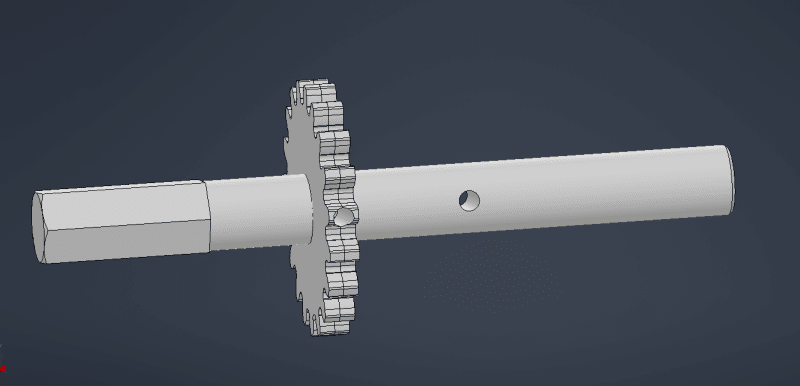
I am working on a functioning prototype that is very similar to what the final result will be. You can see in the attached image, my gear laminates that would be braze welded together, are drilled through so that a small roll pin can fix them to the shaft during assembly. Some time later the caffeine kicked in and I realized what a nightmare this hole will be to drill. By that point I had already designed the entire rest of the assembly around this drive shaft, so my options are limited on what changes I can make. The task at hand is that I need a way to attach these gears (will likely be a single thicker gear in production) using some method that can be done during final assembly with hand tools. Using a key seems easy, except I have a bearing directly on either side of the gears so the key can only be cut as wide as the gear thickness, and I've never seen it done like that. 5/8 dia shaft, gears are roughly 1/4 thick total.

If a redesign is in order then it is what it is but after the latest department meeting everyone liked this design, minus the obvious flaw, so I am hesitant to change more than I have to.
 
Replies continue below

Recommended for you

Continue the Hex and then you only need to locate it and not lock against rotation?
Short keys are used in low load applications, it should work here.

= = = = = = = = = = = = = = = = = = = =
P.E. Metallurgy, consulting work welcomed
 
What is the point of the gear laminates? You will not attain brazing perfection and one laminate will carry the load.

Does this thing run in one direction?

Choose your constraints - are bearing locations more important than power transmission? There are plenty of options with bushings/hubs or shaft-locking devices, but they need to dictate where the bearings locate. Also, the hex shaft appears larger than the round and, thus, won't slip through your bearings at assembly. You need to take a critical look at the assembly requirements. It wouldn't hurt to show a cutaway sketch of your assembly for further comments.
 
"What is the point of the gear laminates? You will not attain brazing perfection and one laminate will carry the load." These gears are parts that we already have on hand and braze thousands of a day. Having two of them gives us a total thickness similar to what I have drawn up for the final design.

"Does this thing run in one direction?" Both directions.


"Choose your constraints - are bearing locations more important than power transmission? There are plenty of options with bushings/hubs or shaft-locking devices, but they need to dictate where the bearings locate. Also, the hex shaft appears larger than the round and, thus, won't slip through your bearings at assembly. You need to take a critical look at the assembly requirements. It wouldn't hurt to show a cutaway sketch of your assembly for further comments." It is a bit hard to see in the cross section but the outer housing locates the bushings which in turn locate the gear. At the moment this assembly is very simple and compact, and I am trying to keep it that way as much as I can.

To assemble, you stick the smooth end of the shaft through one side of the two part housing, 1st bushing, gear, 2nd bushing, 2nd housing, then on to the rest of the assembly.
 
that hole down a tooth seems "madness" !

why not two rivets ? align the two gears, clamp, drill holes of rivets (like through the face to the gear), bang in a rivet (and the two gears should be one).

this joining is only temporary, right ? in the final installation both gears are brazed onto the shaft ?

how confident are you that any two gears will align ? This wasn't part of the original design, no? Maybe "someone" should do a GD&T study >

"Hoffen wir mal, dass alles gut geht !"
General Paulus, Nov 1942, outside Stalingrad after the launch of Operation Uranus.
 
It would sure help if the rest of us had some idea of the sort of loading that this mechanism would see, or even some indication of its scale, and whether future disassembly is a consideration.

1. Interference-fit, and press the gear onto the shaft (heating the gear and/or cooling the shaft to facilitate assembly).
1a ... against a step in the shaft.
1b ... using a fixture to assemble it to the correct position on the shaft.
2. Spline the length of the shaft, or at least through to where the gear is, and locate the gear between two circlips, or against a step in the shaft with a circlip, or against a collar on the shaft with a circlip.
3. Use a taper-lock collar. Numerous designs are commercially available.
4. Machine a taper on the inside of the gear and a corresponding one on the shaft, and ...
4a ... press it in place.
4b ... securing tension on the taper using a threaded collar.
 
put a step on the shaft, to help align the gears (to the right location).

"Hoffen wir mal, dass alles gut geht !"
General Paulus, Nov 1942, outside Stalingrad after the launch of Operation Uranus.
 
lucky-guesser said:
Using a key seems easy, except I have a bearing directly on either side of the gears so the key can only be cut as wide as the gear thickness, and I've never seen it done like that

Did you consider a woodruff key?

Regards,

Mike

The problem with sloppy work is that the supply FAR EXCEEDS the demand
 
If torque is low enough put a split clamp on the shaft that has tapped holes (axially - parallel to shaft axis). Drill corresponding holes through gears.
 
Some simple options are:
1. Shrink-fit the gear on the shaft. Usually it's easiest if the shaft has shoulders to axially locate the gear or other elements on it (or you can use sleeves as well). It's also easier to mount a shrink-fit if the shaft in front of the gear is slightly smaller so it doesn't have an interference fit with the gear for the entire length.
2. Use a parallel key with straight ends that has a length that is slightly smaller than the width of the gear. The keyseat can continue underneath the bearings (although this isn't ideal). The key doesn't have to be a standardized length, it can be made from cold drawn steel with the right width and height and just made to the correct length. It can also be made from a stronger steel than the standardized keys if necessary.
You can also use a key with a shrink-fit if the gear has to be located rotationally in a certain location on the shaft but a key by itself isn't strong enough or you can use 2 keys.
3. If the bore in the gear can be tapered you can use a bearing adapter sleeve.
4. If the gears can have a wider hub it's possible to use a set screw or radial pin there so there's no need to drill the entire radius of the gear.
 
Thx MintJulep, might work, might not. Only the Shadow knows :)

The problem with sloppy work is that the supply FAR EXCEEDS the demand
 
thermal fit seems best to me, tho' quite problematic. I guess you could make the shaft over long, install the gear near where you need it (maybe having a tool mounted on the shaft ?) then trim the shaft so the position of the gear is controlled. You might have a tool (at RT) so that you can (quickly) install the cold shaft, then quickly position the (hot) gear on the shaft in a controlled position.

Braze the gears together if you like, but this'll limit their temperature. Joining them with double flush rivets should be easy.

"Hoffen wir mal, dass alles gut geht !"
General Paulus, Nov 1942, outside Stalingrad after the launch of Operation Uranus.
 
lucky: From the way you've sketched your initial concept, this is a throw-away construction after the OEM makes it the first time. Using a radially-oriented pin to locate/lock the gear in position means you won't be able to remove/replace the inner bearing next to the hex end of the shaft. Much better to use a stepped shaft approach with interference fit on diameters to locate components. After all, you're going to be using this method for each bearing anyway. Bearings (and gear) can be heated prior to shaft insertion. If you don't have enough diameter in the shaft to create physical steps and there IS room to move things around a bit axially, consider implementing a small spacer ring between each bearing and the gear itself, to give a "shoulder" for positioning purposes (spacer ring would not need the same interference fit required of the gear and/or bearing).

Converting energy to motion for more than half a century
 
Similar to thermal fit - simply stake the part - a series of dents into the faces of the gears near the bore to squeeze the inner diameter onto the shaft.
 
I would add a shoulder and threads to the shaft, clamping the stack with a thin-section nut to ensure you have a solid connection. Keys and set screws are for alignment and assembly, they're terrible for applying torque.
 
Status
Not open for further replies.
Back
Top