I have what may be a simple question, I don’t know if I’m just overthinking this. I am looking through the test data of Torque twist curves on a couple shafts. Yield and rupture torque seem more straightforward. However I would like to compare toughness between various shafts. I understand for a stress strain curve that toughness will be the area under the curve. Toughness determination does not seem as obvious to me, for shafts with varying cross section.
Using the area under the curve of the torque-twist diagram seems like it would be flawed because the sections of the shaft that have different cross sections will be straining at different rates, and the overall twist is heavily dependent on the length of each cross section.
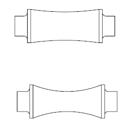
I’ll give a hypothetical example to help illustrate my point. I’ve sketched up two shafts. For discussion purposes ignoring any stress concentrations, and assume the shaft is in pure torsion. The shafts are simpler than the ones I’m dealing with but the principle is the same. On both shafts the ends are the same diameter. The first shaft has a relatively large diameter in the middle of the shaft, the second shaft slopes down to a diameter just slightly larger than on the ends. Both shafts should rupture at the same torque since the smallest diameter on the ends is the same. The Second shaft will overall have much more twist, since the smaller diameter in the center will twist much more than the larger diameter on the first shaft.

If I take the area under the curves for the torque twist diagrams, it would seem that the second shaft is much tougher than the first. Would this actually be the case? Is having a smaller diameter in the center actually making the shaft effectively tougher, as there is more overall twist available before rupture? Or would they both be similarly tough in function because the strains at the the ends are still the same—since they’re still the same area cross section and under the same torque? Or am I off base on all of this?
Ideally I’d like to convert the curves from Torque-twist to stress-strain, but I’m not 100% sure how to do this, especially for the plastic region.
Thanks in advance for the help!
Using the area under the curve of the torque-twist diagram seems like it would be flawed because the sections of the shaft that have different cross sections will be straining at different rates, and the overall twist is heavily dependent on the length of each cross section.
I’ll give a hypothetical example to help illustrate my point. I’ve sketched up two shafts. For discussion purposes ignoring any stress concentrations, and assume the shaft is in pure torsion. The shafts are simpler than the ones I’m dealing with but the principle is the same. On both shafts the ends are the same diameter. The first shaft has a relatively large diameter in the middle of the shaft, the second shaft slopes down to a diameter just slightly larger than on the ends. Both shafts should rupture at the same torque since the smallest diameter on the ends is the same. The Second shaft will overall have much more twist, since the smaller diameter in the center will twist much more than the larger diameter on the first shaft.

If I take the area under the curves for the torque twist diagrams, it would seem that the second shaft is much tougher than the first. Would this actually be the case? Is having a smaller diameter in the center actually making the shaft effectively tougher, as there is more overall twist available before rupture? Or would they both be similarly tough in function because the strains at the the ends are still the same—since they’re still the same area cross section and under the same torque? Or am I off base on all of this?
Ideally I’d like to convert the curves from Torque-twist to stress-strain, but I’m not 100% sure how to do this, especially for the plastic region.
Thanks in advance for the help!
