Continue to Site

Eng-Tips is the largest engineering community on the Internet

Intelligent Work Forums for Engineering Professionals

  • Congratulations KootK on being selected by the Eng-Tips community for having the most helpful posts in the forums last week. Way to Go!

Shallow foundations: distribution of soil pressure with Eurocodes

Status
Not open for further replies.

Lhi

Geotechnical
Nov 22, 2019
8
Hi,

I work in a French office and I have questions about foundation design with EC7 and EC2.

I'm studying column foundations with eccentricity to program an Excel sheet.
I configured Meyerhoff, trapezoidal and triangular pressure distribution for combined bending to verify the soil pressure under foundations.

Now I'm programming the reinforcement which is define by struts and ties method if the footing is rigid or bending moment if it’s not the case.

I found in several documents that the reinforcement in ULS is calcultated with a rectangular distribution of the pressure which means Meyerhof's method. But I don't know why.

In fact, with EC7 the pressure under the footing is verified with SLS and ULS. So, we usually start to verify SLS before ULS with EC7.
If we choose the triangular or trapezoidal method (depending on the value of eccentricity) for SLS to otpimize cross sections, is that correct to verify with Meyerhof in ULS? Is it not strange to mix the 2 methods even if SLS is an elastic calculation and ULS a plastic one? Or can we verify ULS with trapzoidal or triangular diagrams? And what about reinforcement? Is it correct to use Meyerhoff's method in SLS?

What is the best engineering practice?

Thank you in advance for your help, I'm a little bit confused about the choice of diagrams..

 
Replies continue below

Recommended for you

I believe not many people here are familiar with EC7 and EC2. A drawing/sketch indicating footing shape, and pressure diagram may draw more eyes and responses to your concerns.
 
Thank you for the answer.
For a shallow foundation with bending moment in one direction we can have a trapezoidal or triangular soil pressure depending on eccentricity value :

2_ona0rz.jpg


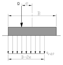
The NF94-261 is an annex of Eurocode 7. We find that Meyerhof’s method can be used to simplify the distribution soil pressure under footings but it's unfavourable for cross section:

images_wfwtej.png


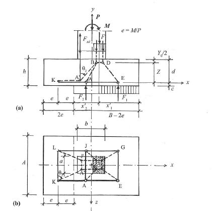
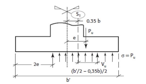
I'm studiyng shallow foundations with trapezoidal or triangular pressure distribution. I have to calculate reinforcement with this non uniform distribution but here are extracts (from french books) of pressure diagram used for it:

-Reinforcement with strut and ties's method:
strut_c8ek8r.jpg

-Reinforcement with bending moment's method:
be_fzu5xb.jpg


For both methods, hypothesis of soil pressure is the same: it is a rectangular diagram. How is it possible to take this hypothesis if the cross section of the footing was previously designed with a triangular or trapezoidal pressure distribution ?

I can't find any example of a shallow foundation reinforcement designed with a non rectangular soil pressure diagram...

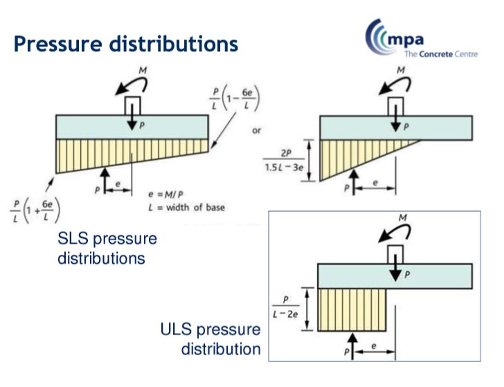
Here is another extract from an english document which describes the diagram of pressure distribution for each limit states:
j_d4mldz.jpg

But i don't know how this choice is justified?

Thank you for your help.
 
If you noticed and understood the difference of the two abbreviations describing the pressure diagrams in the last graphic, you shouldn't have puzzled over which method is justified for 1) bearing pressure checking (an exact analysis), and 2) footing reinforcing design (an approximation/simplification to produce most conservative design). Make sense?

I personally don't like strut and tie method, with the exception of checking shears in deep concrete members. But the French method seems interesting.
 
Thank you for your answer. This is why I’m asking I’m not sure to understand.
My question is, if reinforcement methods are not describ for a linear diagram( trapezoidal or triangular) and only uniform, is there any sens to optimize the cross section of shallow foundations with trapezoidal and triangular methods for geotchnical checking? It seems that finally we have to choose Meyerhoff diagram to have a coherence for geotechnical and concrete checkings, right?
 
In my opinion, there's no contradiction in using different diagrams for SLS and ULS conditions as the strain level is fundamentally different. More or less like RC section analysis, where you use a triangular stress strain diagram for service conditions and a rectangular stress block for ULS design.
 
Lhi,

I see your discipline is "geotechnical", so you understand well that soil never behave in any way "linear", nor "uniform", therefore, both diagrams (of SLS and ULS) only represent the best approximations that are quite close to the ideal responses of soil, yet remain easy for computation purpose.

The structural engineer like to think the soil is an elastic medium, thus, under service load, the stresses are derived through p = F/A +/- M*y/I, the resulting pressures are linear in forms of triangular or trapezoidal shape. The pressures are consider the exact (not true) solutions of the given conditions, they are then used in calculating the resultant force (R), determine its location under the footing base in contact with soil, and finding eccentricity (e) between the applied load and the resultant force. The maximum pressure and resultant force are thereafter to be used to check the serviceability requirements - namely, bearing pressure, overturning stability, and shear friction between footing-soil interface. This analysis method used to be called "limit equilibrium method", now is more clearly named as "service limit state" (SLS).

Although the primary usage of pressures stated above is checking serviceability, there is nothing wrong to use the pressures in design the footing depth and reinforcing. The dilemma lies in how to properly apply load factors as required in reinforced concrete design by ultimate strength method, a long heated debate I don't want to bring it up in here again. Thus, the uniform pressure distribution is a simplification that more suitable for the purpose of footing design (thickness and reinforcing). The name "ultimate limit state" (ULS) states its intend application clear and loud.
 
Thank you for your help.

@retired13 I agree, thank you for your explications. (I made a mistake when I create my account, I'm structural engineer; I will correct it right away ;-)).
 
I'm not familiar with the Eurocode, so please keep in mind that my responses will be as per US code.

First, soil behavior is more "plastic" at the ULS, while it exhibits a more linear behavior in the SLS. That is why the load distribution assumptions changes between both limit states.

While I can understand why the use of the ULS limit state makes sense (as the load distribution would most likely resemble the ULS distribution during high loads), it is interesting to note that the AASHTO code states that the structural design should be performed based on a trapezoidal (or triangular) distribution.

Untitled_i6zu9o.png


At the end of the day, an assumption has to be made on whether (at the point at which the structural failure would occur on the footing) the load distribution is closer to plastic or to elastic. My completely unsubstantiated opinion is that, because AASHTO has a much more conservative resistance factor (φ) for bearing pressures than for concrete in bending, they assume that the soil will be mostly elastic at the point of structural failure. That being said, you'll have to use whatever assumptions/models your building code states.
 
It is my opinion, that except for some cohesive soils, the soil under load will not become plastic, it just settles more until a new equilibrium is reached.

Also, the soil does not know the acting load is "service load", or "ultimate load", it just settles less or more. However, in anticipation of larger settlement at the ultimate state, the allowable bearing stress was given (by GT) with a safety factor greater than the load factors to be applied in the ULS, to ensure in-situ soil capacity will not be exceeded at either case (SLS or ULS). This paragraph is open to comments from the geotechnical engineers.

I don't know why AASHTO sticks with the design using factored pressures derived through limit equilibrium method (I think BridgeSmith could provide insight on this). It is awfully difficult to track effect of each load, and maintain the location of the resultant force as determined by non-factored (service)loads. It had been a lengthy debate on this, at the end of the day, for practical reasons, most engineers either resorted to using the uniform (simplified) pressure diagram, or derive a single (weighted) load factor to be applied to all of the service loads. Many of the old structures, designed by any method mentioned above, still stand. So, judge yourself, which is better.


Status
Not open for further replies.

Part and Inventory Search

Sponsor