Continue to Site

Eng-Tips is the largest engineering community on the Internet

Intelligent Work Forums for Engineering Professionals

  • Congratulations KootK on being selected by the Eng-Tips community for having the most helpful posts in the forums last week. Way to Go!

Shear Analysis

Status
Not open for further replies.

njm789

Automotive
Oct 9, 2019
25
Hi All!

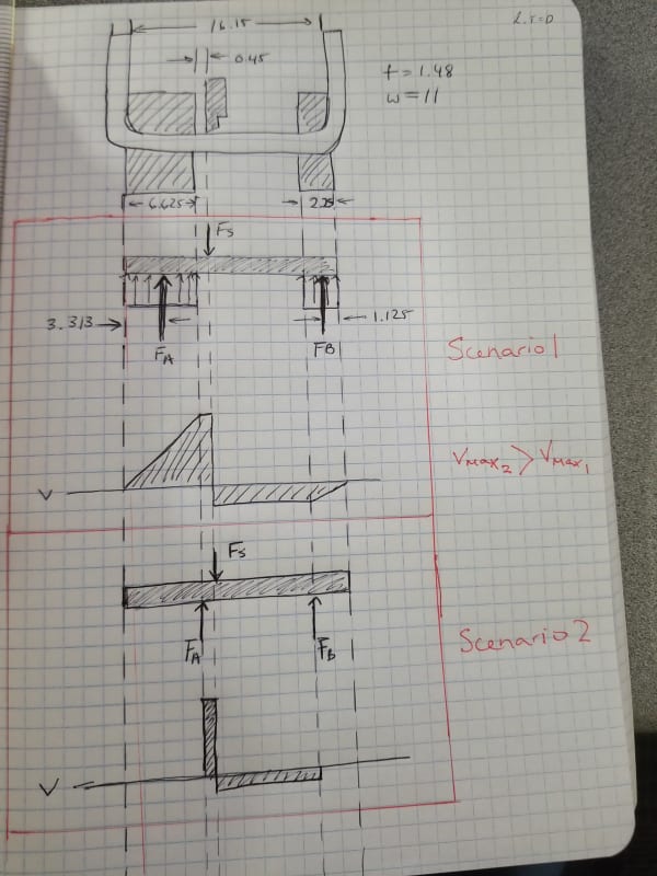
I'm designing for a strip of metal (b=11, h=1.48mm) to fail in shear. Its a pyro safety switch where a piston is forced to shear the strip and bend the flap of metal to create distance between the two pieces. I want to find the shear stress for a given force. I have attached an image of my analysis. I am not sure if I can simply assume the reaction forces act at the end of the supports or if I need to use a "distributed load" for the reaction forces (take the force to act at center of load). This gives different shear force diagrams so I was wondering which would be more correct. I am looking to use Tau=Vq/IT or would average shear Tau=V/A suffice? Thanks in advance.
shear_fi4krw.jpg
 
Replies continue below

Recommended for you

I think scenario 1 is a better representation.

I think scenario is misleading in that it doesn`t line up with scenario 1 (Fa and Fs particularly).
Scenario 1 would give you a misleading BM.

Scenario 3, with support A being a triangular dist`n peaking near Fs may be closer. But this doesn`t change the shear.

Assuming a section Wt reacts Fs is reasonable. To be sure of failure, you`ll need to do some testing (material allowables are usually conservative).
You may get "better" results if you score the section being sheared.

another day in paradise, or is paradise one day closer ?
 
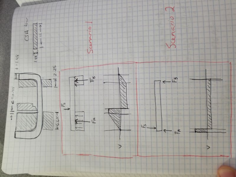
thanks rb1957! Sorry, my forces for scenario two are not lined up correctly. The second scenario would take the "inside edges and create a simply supported beam case. This in turn yields a higher shear force than scenario one. I have done some testing and the force to shear the strip is much higher than calculated. This was using shear force from scenario 2. I may try the triangle distributed support. Thanks for the suggestions!
shear_b1f4px.jpg
 
ok … don't bother with the triangular dist'n … it'll fit between these two extremes.

How much did the test piece bend ?
How much did it tear (ductile failure) ?
What metal ?
How fast is the shearing action ?

Try scoring the section to fail.

another day in paradise, or is paradise one day closer ?
 
So from preliminary trials, we could not shear the strip. The piston is only short and as the material begins to bend it imposes a side load on the piston which causes it to move away from the lower shearing edge. This increases the clearance between the two shearing edges which results in the strip bending over the edge a little and due to a limited stroke (4mm) the strip just bends not shears. The material is c110 1/4 hard. I was thinking maybe a material with less %elongation would help. I am creating a fix to guide the piston straight. I believe the clearance also may be causing the increase in force needed to shear. As for the scoring, the strip is scored though I am limited by electrical criteria the strip must meet.
 

The expected maximum shear force should P max = 0.7*w*t*ftmax

ftmax= maximum tension strength

As far as i understand , the piston sharp edge is paralel to the metal sheet. That is, the force is applied to the bending weak axis of the sheet.

Try with a piston which has inclined sharp edge and with minimum clearance (in your case 0.45). Remember paper puncher, the piston punches two small holes then shear propagates.

Good Luck...
 
Status
Not open for further replies.

Part and Inventory Search

Sponsor