Continue to Site

Eng-Tips is the largest engineering community on the Internet

Intelligent Work Forums for Engineering Professionals

  • Congratulations cowski on being selected by the Eng-Tips community for having the most helpful posts in the forums last week. Way to Go!

Shear at support of continuous beam

Status
Not open for further replies.

simples123

Structural
Apr 15, 2019
3
I've often used this site for advice but this is my first time posting here! I'd like to hear your take on a debate a friend and I have had regarding shear at the intermediate support of a continuous beam.

The argument is about whether one should design the shear at the central support of a continuous beam for the total reaction under the support or for the maximum shear calculated from the shear diagram.

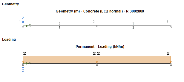
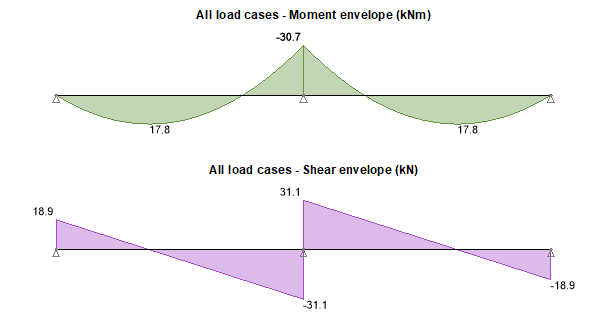
By way of example see the attached images. A beam consisting of 2no. 5m spans, all supports pinned. 10kN/m UDL applied to the beam (RC beam 300x800mm deep). Based on this the shear force is +/- 31.1kN at the intermediate support. The total reaction at this support is 62.2kN. Should the beam be designed for an applied shear of 31.1kN or 62.2kN?
Continuous_beam_geometry_ygsajo.png

Continuous_beam_shear_lzeace.png
 
Replies continue below

Recommended for you

The reaction at the central support is 62.5 kN. The shear in the beam each side of the central support is 31.25 kN. The beam is designed for a shear of 31.25 kN, reduced as appropriate to account for the width of support and depth of the beam.

BA
 
The argument is about whether one should design the shear at the central support of a continuous beam for the total reaction under the support or for the maximum shear calculated from the shear diagram.

Beam shear is 1/2 of the total reaction in this case....31.1 kN.
Per BAretired, in many codes you can reduce the beam shear further by taking the shear at a distance d from the face of support. (d = design depth of the beam from compression face of beam to centerline of reinforcement).


Check out Eng-Tips Forum's Policies here:
faq731-376
 
Thanks BA,

Glad to hear i'm not going mad. I thought this was structural engineering 101 and yet my friend who is a much more experienced engineer was adamant that you should design for 62.2kN in this case. How do you think I should try and explain this to them? I've tried a number of ways but am evidently not persuasive enough! They tried to provide an analogy to slab punching shear (i.e. you use the total column reaction when calculating the shear stresses in this case) which I can only see being relevant for a sort of face shear failure of the support and I can't ever see this being a governing failure.
 
there are two shear faces supporting the reaction load, so each shear face sees 1/2 (as the others have noted).

another day in paradise, or is paradise one day closer ?
 
The punching shear analogy should point back to your point though - punching shear is considered about the entire failure perimeter. In your case, you have a beam that had two failure planes, one on each side of the column, each resisting half the total reaction. For punching shear of a two way slab, you have 4 failure planes each resisting 1/4 of the total reaction.
 
structSU10,

Thats exactly how I tried to counter argue that point. If you make a flat slab so narrow that it can no longer develop a punching shear plane on all 4 sides then you are left with a continuous beam of sorts with the two shear planes. I just don't understand where they are coming from and why I am unable to convince them! Super frustrating
 
simples123 said:
I thought this was structural engineering 101 and yet my friend who is a much more experienced engineer was adamant that you should design for 62.2kN in this case. How do you think I should try and explain this to them?

He may be a more experienced engineer but his experience does not seem to be in structural analysis and design. I don't know how you should explain it to him; you could suggest a review of his old text books.

BA
 
Ask your colleague to draw a FBD of any segement of the beam that would indicate a shear greater than 31k. He or she will not be able to and, unless they don't believe in free body diagrams, should find that fairly persuasive. Sometimes the onus of proof needs to be shifted to the party in error.
 
What is the support? If it's a column, the total reaction in the column is 62.2. If it's bearing on something, then the total bearing force is 62.2.

It's just the beam never sees the full amount, it only sees the half from each side.
 
Failing all the other good advice that's been given, tell him the internet said so.....

Kootk's suggestion should enable him to either prove himself wrong, or invent some new branch of physics where sum of the forces in the vertical direction do not equal zero.
 
How to explain it - just look at the shear force diagram of the 2 span beam!
 
As others have said, the reaction at the support is 62.2kN, so if there are no bearing stiffeners, the web will have to support that force, but it's a different capacity calculation from beam shear capacity. With or without bearing stiffeners, the bearing capacity at the support does need to be checked. Perhaps that was what your colleague was attempting to convey.
 
HotRod10 brings up a good question - is this a steel or concrete beam? I was assuming concrete but if steel, then there is the issue HotRod10 points out in terms of BEARING issues and web crippling, buckling, etc. that would involve the total reaction. But shear on any one beam section, as you originally posted, is still 1/2 of the reaction.


Check out Eng-Tips Forum's Policies here:
faq731-376
 
I just took a closer look at the OP's diagram and saw it does say "Concrete" at the top. If you are talking about a concrete beam, then I'm at a loss of what your colleague is thinking.
 
Your colleague is wrong... I don’t know how you could explain it more clearly and I’m not sure I would have the patience to do so with him!! 🤣

Incidentally, say there’s a simple beam 5m long with a 10kN point load at midspan, giving us a simple rectangular shear force diagram of 5kN above and below the line... What shear force would he use for shear design at midspan? 5 or 10kN?!
 
Incidentally, say there’s a simple beam 5m long with a 10kN point load at midspan, giving us a simple rectangular shear force diagram of 5kN above and below the line... What shear force would he use for shear design at midspan? 5 or 10kN?!

Good question.

Or even a 10 m long simply supported span with a uniform downward load of 10 kN/m and an upward point load at mid-span of 62.5kN?

Doug Jenkins
Interactive Design Services
 
Status
Not open for further replies.

Part and Inventory Search

Sponsor