Continue to Site

Eng-Tips is the largest engineering community on the Internet

Intelligent Work Forums for Engineering Professionals

  • Congratulations SDETERS on being selected by the Eng-Tips community for having the most helpful posts in the forums last week. Way to Go!

shear capacity of composite ceiling 2

Status
Not open for further replies.

greznik91

Structural
Feb 14, 2017
186
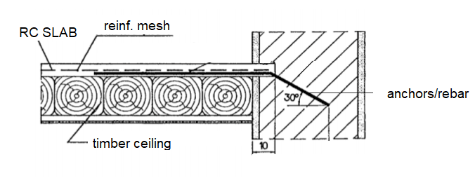
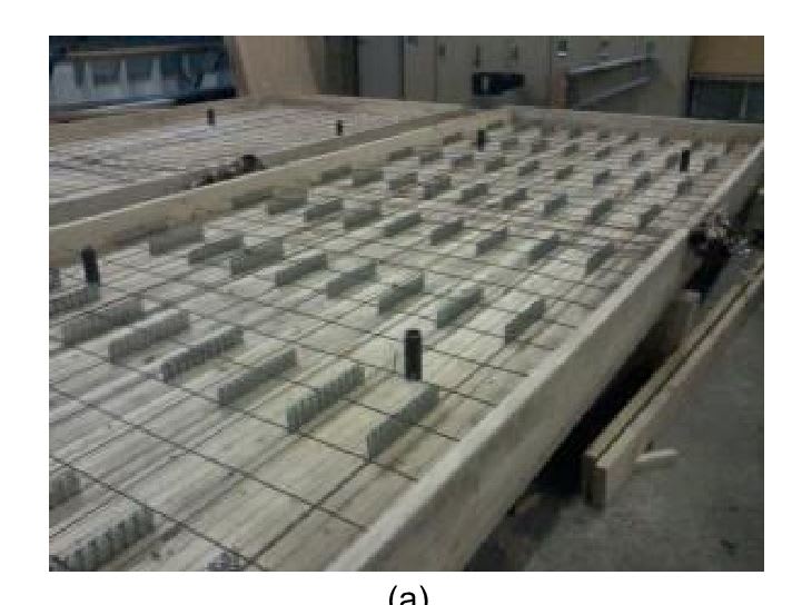
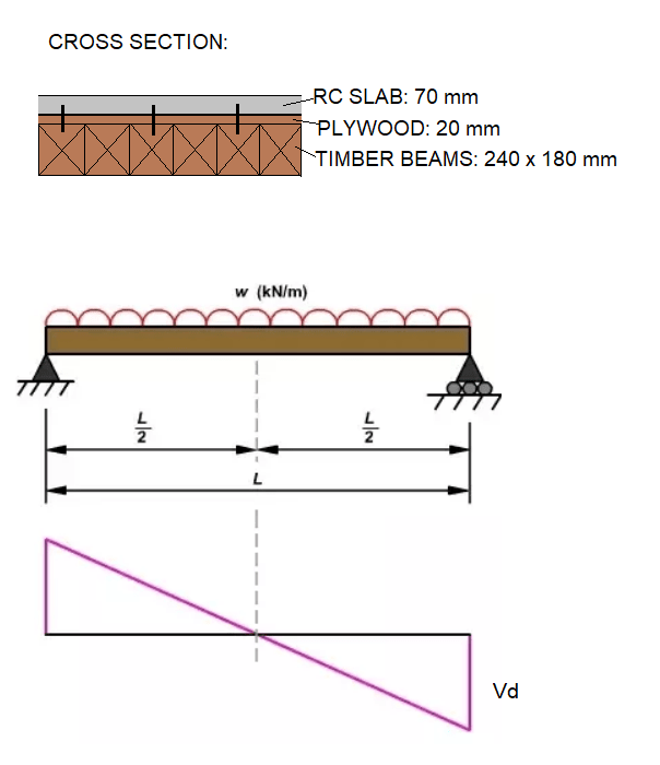
Timber beams 180 x 240 (no spacing between), on top plywood and RC slab (70 mm thic). Connection between slab and timber are nails as shown bellow.
How do I calculate shear capacity per 1,00 m (kN/m) for such composite ceiling?
Q_zq3abr.png


Q2_tfggb9.png
 
Replies continue below

Recommended for you

If it were me I’d be taking the shear capacity of the timber joists only.
 
I'd address as per MIStructE_IRE notes, just take all the vertical shear on the joists.

Although are you potentially meaning to calculate the interface shear between concrete and wood to achieve composite action, and maybe you are not referring to the vertical shear capacity?


Also for the interface shear, your nails would have a tendency to pull out if angled as shown? If you consider the interface between the wood and slab moving relative to one another as the system is loaded, the slab wants to slide [towards the ends of the wood beam] relative to the wood beam. This would have the effect of withdrawing the nails wouldn't it as the interface shear developed (might be designed for this limit state/effect though?). Nails are obviously quite poor in withdrawal compared to loading them in shear. Maybe they are screws though?

My first thoughts are that I'd expect them to be at right angles to the beam surface, least thats what I've seen on previous projects where people have tried to develop some composite action between wood and concrete slabs.
 

I read the thread a few times.. Is the question spacing of nails or the shear capacity of the beam for 1,0 m width ?

IMO, you may calculate both using the transformed section. Typical values for timber Et=9000 mPa Ec= 25000 MPa. and the allowable horizontal shear stress of timber ( around 90 psi) should control the capacity of the composite beam.

Pls provide more info. to get better responds.. Is this a real problem? What is dictating the wooden beams to behave together except the 20 mm thk plywood ?

IMO, if i were in your shoes, i would prefer the floating RC slab. ( 7 mm rc screed + 20 mm hard rockwool + 260 mm timber).


I should have been more clear.
It's an existing thing.
I'd like to calculate vertical shear capacity (kN/m). The most simple way is to consider timber beams only, but I'd like to calculate it for composite section.
If I use transformed section method I should consider connections - screws in (slippage)
 
I must say I’ve never done composite concrete/timber. It doesn’t make sense to me as the rates of thermal expansion are so different. One shrinkage crack and you’re gone!

As I said, I’d still be taking timber only for vertical shear.

Is this a common form of construction where you are? I’ve never come across it before but it looks interesting - more something I’d love to have done as a thesis rather than do in the real world!
 
It's a common thing when reinforcing old structures with timber ceilings.
If old / existing timber beams are in good/acceptable condition we make composite ceiling by putting screws (based on thicknes, material, span and loads for horizontal shear). And then pour concrete slab or screed on top with reinforc. mesh for crack control. Slab is also anchored in bearing walls so it connects bearing walls (acts as diaphragm). It's not what I would do for new structures but it's a common thing for old buildings that are not allowed to be demolished.

ceili_qy766c.png


It doesn’t make sense to me as the rates of thermal expansion are so different. One shrinkage crack and you’re gone

Can you elaborate?
 
Interesting! We would normally do this as a ply stressed skin with a fraction of the dead weight.

If the concrete shrinks and cracks, then presumably at that particular point it has zero shear capacity and you’re left with the shear capacity of the timber only in any event?

Just ignore me if I’m missing something - as I said, I’ve just never seen this before.
 
I second MIStructE's comment, ignore the concrete for shear check. IMO, it is more a burden to the wood beam than help in shear resistance.
 
another vote for ignoring the concrete for shear capacity.

If I understand your reinforcing process correctly this is akin to a composite steel beam where the concrete is used for it's compression block in flexural resistance but the steel beam is assumed to resist the shear.

The method seems a bit counter intuitive to me as the additional dead load from the concrete would seem to be working against you here.

My Personal Open Source Structural Applications:

Open Source Structural GitHub Group:
 
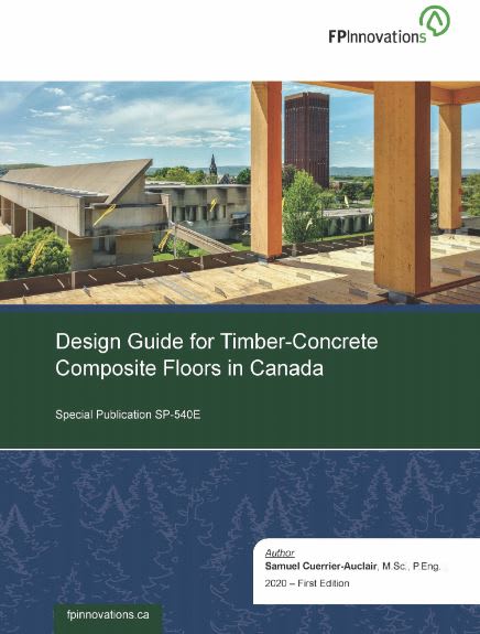
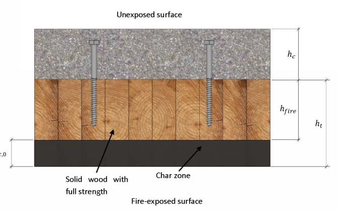
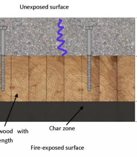
Composite, topped mass timber products are a pretty near analog to this. A relevent design guide, shown below, can be had as a free download. In it, they develop a shear methodology. As OP rightly surmised, much comes down to the flexibility of the connections. And most of the connections considered have been tested to some degree and are considerably more robust than conventional nailing.

C01_kud5ij.jpg

c02_tsz0kb.jpg

C03_hvyzzm.jpg

C04_fhbjpw.jpg
 
Thanks Koot, that’s definitely worth a read.

Pardon my ignorance, but for new builds, why would you choose a concrete topped mass timber floor? I’d have thought the dead weight of concrete eventually reaches a point of diminishing return when compared to a mass timber floor of equivalent depth?
 
MIStructE_IRE said:
Pardon my ignorance, but for new builds, why would you choose a concrete topped mass timber floor?

I'm not an expert on this but I believe that the concrete topping is included primarily to create a finished surface that feels "institutional".
 
Good guide Kootk.

They seem to be saying that the vertical shear that can be carried is either governed by the shear capacity of the interface, or the timber beam alone. So as people have stated, only the bare timber beam should be considered in the normal sense for resisting beam shear, but also just need to confirm you have sufficient shear connection to develop any composite moment capacity required (and the corresponding interface shear which is proportional to the beam shear).

image_rvdhaj.png
 
Got my copy. Thanks, KootK.
 
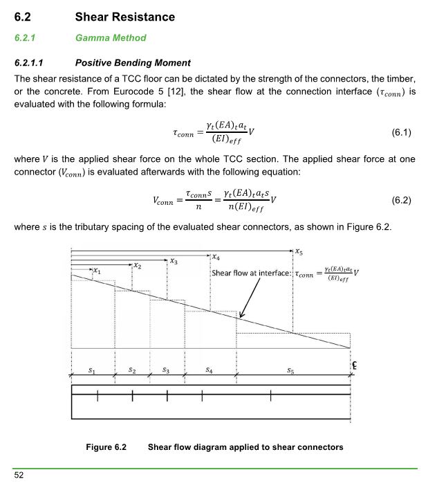
The text is copied from the guide for information. In which, the shear capacity of the composite is dependent of the shear capacity of the connection (shear flow), the concrete, and the timber, respectively.

The shear resistance of the whole TCC floor is reached when the first component reaches its
strength. Thus, the following equation gives the shear resistance of the whole TCC floors (𝑉𝑟):
𝑉𝑟 = min(𝑉𝑟,𝛾,𝑐𝑜𝑛𝑛;𝑉𝑟,𝛾,𝑡; 𝑉𝑟,𝛾,𝑐) (6.16)

In negative bending region,

In negative bending moment, the (𝐸𝐼)𝑒𝑓𝑓 is calculated according to the equation presented in
Section 2.3.5.2. A conservative approach to evaluate the shear resistance of the composite beam
is to neglect the shear force taken by the concrete slab. Consequently, the shear resistance is
evaluated with the following equation:
𝑉𝑟 = min(𝑉𝑟,𝛾,𝑐𝑜𝑛𝑛;𝑉𝑟,𝑡) (6.18)

 
Agent666 said:
They seem to be saying that the vertical shear that can be carried is either governed by the shear capacity of the interface, or the timber beam alone.

It seems to me that they're only saying that for negative moment regions, and for obvious reasons. It appears to me that, for positive moment regions, they are allowing composite behavior to improve shear capacity. I've only really skimmed this document so far, however, so it's entirely possible that I've missed something.

From a mechanics perspective, we know that horizontal shear and vertical shear are complimentary. In that sense, having the gain in horizontals shear pretty much guarantees also having it in vertical shear. That said, a little extra conservatism in the vertical shear is understandable if that's the story that we're telling.

 
So what would a shrinkage (or other) crack here do if we were reliant on the composite section for vertical shear?

FB225C77-85FC-450A-9655-E16093266C4E_icpdzl.jpg


To answer OP’s question, I’m still inclined to take the shear capacity of the timber only.
 
Please note the constrain "minimum of": MIN(Shear Flow, Concrete Shear, Timber Shear). IMO, unless the concrete is very thick and strong, it would not govern in most occasions. (I could be wrong though)
 
MIStructE_IRE said:
So what would a shrinkage (or other) crack here do if we were reliant on the composite section for vertical shear?

1) Nothing so long as one of the following is true:

a) the shrinkage crack is small enough to not compromise aggregate interlock shear capacity and/or

b) the governing shear failure mode occurs on a diagonal plane rather than a vertical one.

2) In my mind, with proper connectors, this is fundamentally similar to these two situations where we normally do allow for shear enhancement as a result of toppings that will have restrained shrinkage cracking:

a) composite concrete slabs cast over metal deck and;

b) composite topping slabs cast over hollow core plank.

 
Status
Not open for further replies.

Part and Inventory Search

Sponsor