Continue to Site

Eng-Tips is the largest engineering community on the Internet

Intelligent Work Forums for Engineering Professionals

  • Congratulations SDETERS on being selected by the Eng-Tips community for having the most helpful posts in the forums last week. Way to Go!

shear capacity of composite ceiling 2

Status
Not open for further replies.

greznik91

Structural
Feb 14, 2017
186
Timber beams 180 x 240 (no spacing between), on top plywood and RC slab (70 mm thic). Connection between slab and timber are nails as shown bellow.
How do I calculate shear capacity per 1,00 m (kN/m) for such composite ceiling?
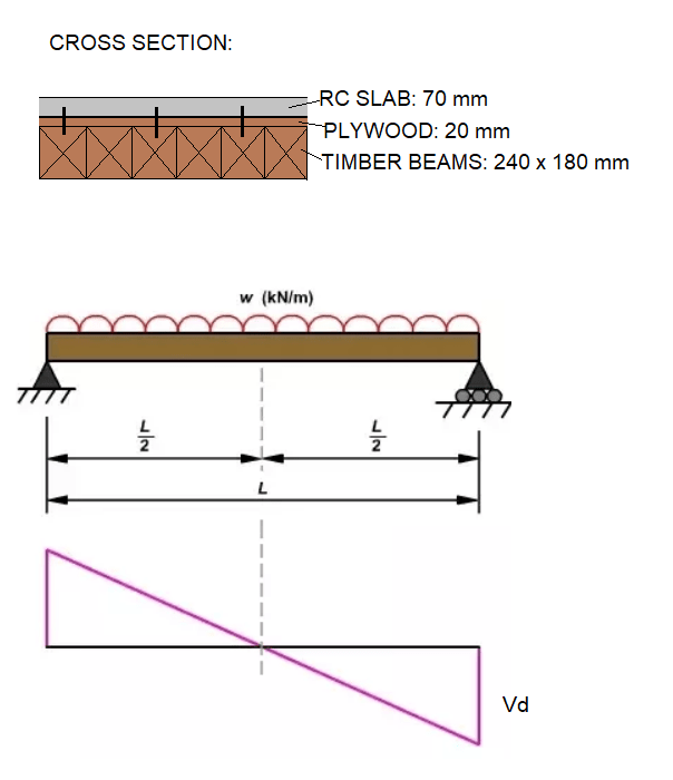
Q_zq3abr.png


Q2_tfggb9.png
 
Replies continue below

Recommended for you

Kootk, yeah you're right actually on further skim reading!

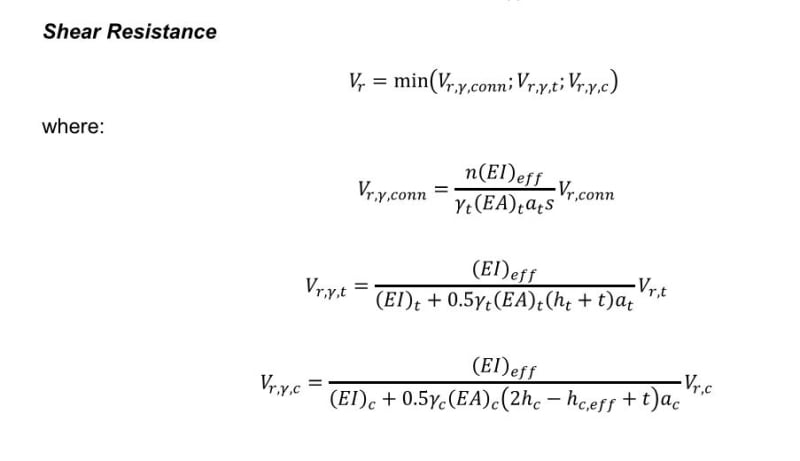
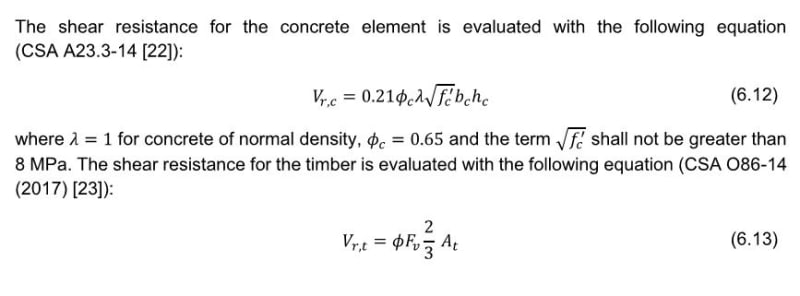
But I'm having trouble determining for positive bending what Vr,t and Vr,c are in equations 6.14 and 6.15, as cannot find it in the guide proper. In the example I think they work through it, but just stated the value for Vr,t (any chance you could confirm thats just the stock standard normal shear capacity for timber.
Being familiar with Canadian ways, are they the individual shear capacities of timber and concrete determined normally on their own in isolation (from appropriate codes, the only equation given in the example is for the Vr,c concrete shear capacity and not sure if that is a capacity just for this purpose or from concrete code or something?)

I'd need to work through the rest of eqn 6.14 and 6.15 to see how much the multiplier might be over any above the bare timber or concrete shear capacities. In the example, the composite shear capacity comes out lower than the bare timber, as it was limited by the concrete shear capacity. I guess it's analagous to a flitch beam, in that you're after the composite capacity when one of the materials/components reaches it's limit.

Hopefully the OP can post back his findings if using this.
 
I’m inclined to agree with you Koot.

As I said, this is a completely new one for me!
 
r13 said:
Please note the constrain "minimum of": MIN(Shear Flow, Concrete Shear, Timber Shear). IMO, unless the concrete is very thick and strong, it would not govern in most occasions. (I could be wrong though)

In the example the concrete governed the shear capacity.
 
Agent666 said:
Hopefully the OP can post back his findings if using this.

In my opinion, OP still won't be able to use this methodology for lack of solid testing & recommendation's for the fasteners he's got. This stuff is fun to kick around, and I try to help where I can, but I still suspect that the path forward for OP will be timber shear capacity alone.

Agent666 said:
Being familiar with Canadian ways...

I'm afraid that I won't be able dive any deeper on this until the weekend, and may not even then if some of the bicycle parts that I have on order show up as planned. When I do a quick scan of the relevant equations, however, they strike me as follows:

1) Stresses calculated based on some manner of partially composite sections.

2) Individual material stresses from [1] compared to conventional limits for those materials.

The equations have that "flavor", you know?

MIStructE_IRE said:
As I said, this is a completely new one for me!

I hear it. If I had to reinvent all of structural design myself from scratch, what I'd come with would be so ridiculously conservative that nothing would ever get built. I still sometimes shake my head that we happily assume that beam shear cracks will happen across stirrups rather than between them. Let's hear it for testing and collective experience!!

C01_u7vwlr.jpg
 
For shear capacity of concrete and timber, see equations 6-12 to 6-15, on p.54-55. I've not get to the example yet.
 
I can confirm that this stuff is standard, uni-material capacity value per Canada's standards.

C01_k4giqj.jpg
 
Thanks!

EDIT - not sure how I missed those 2 eqns, but good to know they are stock standard, as helps with possibly applying logic to other regions.
 
In the example, bc = 1000 mm, I assume it is the effective flange width, does anybody know where the dimension is indicated?
 
Here I have another question, when a concentrate load placed on the slab supported by the timber beam, wouldn't it be a compressive load that pushes the concrete into bearing with the timber? If so, shouldn't the concrete fail in bearing (crumbling/splitting), rather than shear? Can somebody enlighten me on this? Thanks.
 
In the example, bc = 1000 mm, I assume it is the effective flange width, does anybody know where the dimension is indicated?

I believe in the example its a solid plank type CLT floor (184mm x 1000mm wide considered), they are simply working out the capacities based on a per meter width, which is where the b_c of 1000mm comes from. Review the pictures of the arrangement in the start of the example.
 
Status
Not open for further replies.

Part and Inventory Search

Sponsor