Continue to Site

Eng-Tips is the largest engineering community on the Internet

Intelligent Work Forums for Engineering Professionals

  • Congratulations cowski on being selected by the Eng-Tips community for having the most helpful posts in the forums last week. Way to Go!

Shear Deformation - Point Moment 7

Status
Not open for further replies.

Celt83

Structural
Sep 4, 2007
2,083
This is probably something that is very easy and I am way overthinking it.

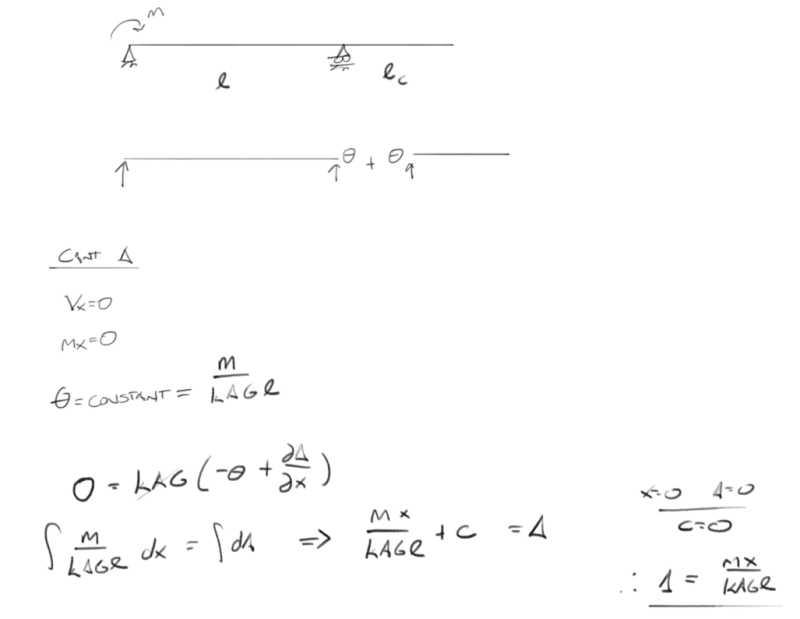
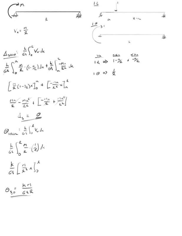
I've done the unit force method which shows that the shear deformation from a point moment is 0 at all locations on a simple span. I've done the same thing to show that the shear component of the slope at any location on the beam is constant = k M / A G L. Here is where I get hung up if the slope is constant and non-zero why is the deflection 0 from a math stand point, the mechanics make sense to me but I'm lost in the math on this one.

I have a great mechanics of materials book by Timoshenko and Young which for me so far has the best break down of shear deformations I've been able to find and in there they present that the slope due to shear is simply dy/dx = tau,max / G = k Vx / A G, which aligns with my unit method solution of k M / A G L.

integrating that once yields: y,shear = k M x / G A L + C1

Initial conditions are x=0, y=0 and x=L, y=0 the first condition yields C1 = 0, however the second condition yields C1 = k M / A G ... so I get that something is missing here which would should result in y,shear = 0 but I am at a loss.

would greatly appreciate any insight on this one.
2_e00mlq.jpg


Open Source Structural Applications:
 
Replies continue below

Recommended for you

If the applied moment is clockwise as in the OP, the cantilever deflects downward, right?

BA
 
looks ok to me … now try your overhang beam (I don't see why, KootK's sketches aside, the shear deflection should change like that).

another day in paradise, or is paradise one day closer ?
 
I think you're rushing the sums (like you did last time).

I don't think this problem is any different to the previous beam (without the overhang).

I think the (unloaded) overhang deflects (like a Euler beam) … continuing the initial slope.

another day in paradise, or is paradise one day closer ?
 
rb1957 said:
I think you're rushing the sums (like you did last time).

I don't think this problem is any different to the previous beam (without the overhang).

I think the (unloaded) overhang deflects (like a Euler beam) … continuing the initial slope.

- yes I was

- Agreed on the last two points

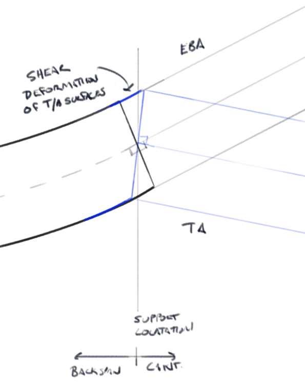
sketch below is how I understand it:
Black is traditional Euler-Bernoulli Behavior
Blue is Timoshenko Behavior

Under the point moment (Torque) the top and bottom surfaces of the cross section deform horizontally this changes the rotation of the cross section vertical axis. When you get to the unloaded cantilever there is no load on the beam to cause any additional deformation so the line of deformation remains perpendicular, normal, to the cross section vertical axis so the cantilever maintains the initial cross section rotations throughout and the deflection is simply the distance from the support multiplied by the rotation.

Capture_u09xbu.png


Open Source Structural Applications:
 
why would the overhang deflect down due to shear ?

the overhang is really (IMO) doing nothing to react the load. it is (literally) the tail on the dog … doing whatever the beam wants it to do, without affecting how the beam does it's job.

now if there was a 3rd support at the end of the 2nd span, that would be different (to the original single span beam).

another day in paradise, or is paradise one day closer ?
 
rb1957 said:
why would the overhand deflect down due to shear ?

For exactly this reason:
rb1957 said:
it is (literally) the tail on the dog … doing whatever the beam wants it to do, without affecting how the beam does it's job.

The inclusion of the shear deformation introduces a new rotation of the cross section in the case of the clockwise point moment (torque) this rotation is constant and counter to the rotation caused by bending when you get past the point of maximum deflection in the back span. So when you get to the right support the rotation of the cross section is such that the normal axis is now pointing down instead of up.

Open Source Structural Applications:
 
calc as you will but I see nothing to change the slope of the overhang.

another day in paradise, or is paradise one day closer ?
 
Something is wrong here!

Shear deflection of the cantilever may be as shown in KootK's sketch, but total deflection (bending plus shear) cannot be as shown in the computer output by Celt83 on May 2nd at 15:15. Surely the net deflection is primarily due to bending, not shear. I am questioning the output labeled "Bending plus Shear Delta" in that post.

BA
 
BA:
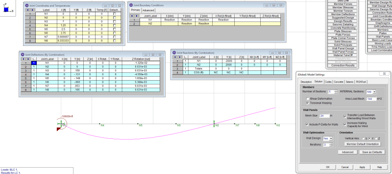
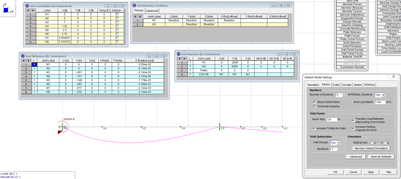
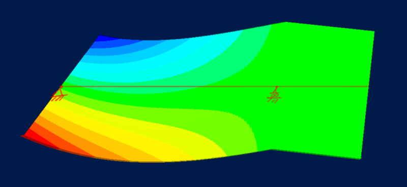
That is the bending plus shear deflection and is certainly an extreme case. The applied moment is 10,000 ft-kips main span is 5ft and the cantilever span is 2 ft. The short span and large loading was my attempt to make sure the deformations of the beam were greatly impacted by shear deflections as to make them more obvious.

Same analysis done with RISA-3D:
bending only:
Capture_uq39gc.png


bending+shear:
Capture_jj7sjo.png


Open Source Structural Applications:
 
@Celt83,

Okay, under that unusual loading, I withdraw my objections.

BA
 
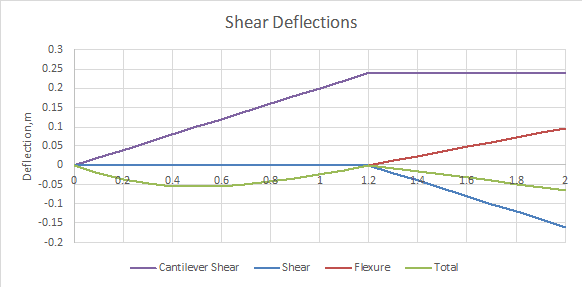
For me, the simplest way to look at this is still to find rotations for a cantilever, fixed at the point of moment application, then rotate so that deflection at the other support is zero:

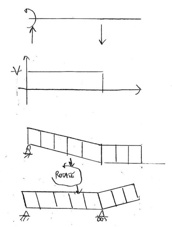
Shear_deflections_dv6c9v.png


Line 1. Find shear deflections for a cantilever fixed at the left hand end, with an upward force of M/L at the right hand support. Vertical sections will remain vertical, but over the region of constant shear there will be a constant upward slope. To the right of the right hand support there is zero shear, so the beam remains horizontal.
Line 2. Rotate so that deflection at the right hand support is zero. The beam is now horizontal between supports, with the right hand end sloping down.
Line 3. Calculate deflections due to flexure only.
Line 4. Add Lines 2 and 3.


Doug Jenkins
Interactive Design Services
 
KootK said:
The part of this that has been nagging at me has been reconciling how the beam "knows" in any given situation whether or not shear strains should produce a vertical straining or a horizontal straining. As shown in my little sketches, I'm able to come up with an algorithm that accurately predicts what will happen based on enforcing compatibility between the boundary conditions and the anticipated shear strain. But predicting is not quite the same as knowing why.

You just need to look at the end conditions.

For the cantilever loading the fixed end section will remain vertical, so all the other sections remain vertical, and shear deflections can only be vertical, with regions of constant shear having constant slope. When it is rotated the shear strains do not change, but the sloping part of the beam is rotated to horizontal, and the end horizontal part is given a slope.

Doug Jenkins
Interactive Design Services
 
IDS said:
For the cantilever loading the fixed end section will remain vertical, so all the other sections remain vertical, and shear deflections can only be vertical, with regions of constant shear having constant slope. When it is rotated the shear strains do not change, but the sloping part of the beam is rotated to horizontal, and the end horizontal part is given a slope.

I disagree:

IDS said:
end section will remain vertical, so all the other sections remain vertical, and shear deflections can only be vertical, with regions of constant shear having constant slope.

I believe that point moment will induce horizontal shear deflections or, more precisely, longitudinal shearing strains along the length of the member.

IDS said:
When it is rotated...

This rotation never actually occurs physically. For me at least, it was always just visualization tool allowing me to predict behavior. This is part of why I sought a more fundamental explanation, such as the energy based theory that I described previously.


This rotation never actually occurs physically. For me at least, it was always just visualization tool allowing me to predict behavior. This is part of why I sought a more fundamental explanation, such as the energy based theory that I described previously.

But if you actually applied the cantilever loading, then released the end rotational fixity whilst maintaining a constant moment and rotating the beam to horizontal (between the two supports), the rotation would actually occur, and you would end up with exactly the same loading as if you had applied the moment directly to the simply supported beam.

But if you don't want to do a rotation, imaginary or otherwise, then you know that the beam between supports must be horizontal, and since the shear force is constant the bottom surface must remain straight (for shear deformation), the shear deformation can only be horizontal.

Doug Jenkins
Interactive Design Services
 
IDS said:
But if you actually applied the cantilever loading, then released the end rotational fixity whilst maintaining a constant moment and rotating the beam to horizontal (between the two supports), the rotation would actually occur, and you would end up with exactly the same loading as if you had applied the moment directly to the simply supported beam.

Part of the problem may be that I simply don't understand the situation that is forming the basis of your mental experiment:

1) Are you talking about the back propped cantilever OP has described or a true cantilever with no backspan and full fixity? I've been assuming the former.

2) OP's cantilever does not have fixity, only a moment.

3) OP's cantilever doesn't have any loading on the cantilever.

I know you're a smart guy so this is just a misunderstanding. But I can't respond to what I don't understand. It might be sketch time if you wish to continue with this.

IDS said:
and since the shear force is constant the bottom surface must remain straight

In my opinion this is something that you have assumed and not proven. Certainly, I agree with the outcome, however, as this is a corollary to what I've attempted to prove with my energy based theorem. As I understand things, a constant shear merely makes for a constant shearing strain. It say says nothing about whether that strain will be perpendicular to the member axis or parallel to it. Hence my quest for the "why".


Koot:

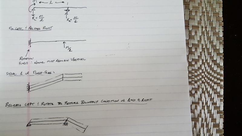
I believe IDS is saying look at it as a fixed-free beam and then restore the boundary condition of deflection = 0 at the right support by releasing and pivoting about the left support.

IDS hopefully I understood this right and it seems to make a lot of sense.

20190504_115142_qcyxnu.jpg


Edit: I think this lines up with your sketches Koot. Also I like your energy theory. Wish this topic was covered in a bit more detail in textbooks I found one book that I might purchase but its a bit pricey compared to some of my other recent purchases. [url ] link [/url]


Open Source Structural Applications:
 
Status
Not open for further replies.

Part and Inventory Search

Sponsor