If you are designing a wood beam with bending in two directions (strong axis and weak axis), how come you only need to check the shear stresses in each axis independently? Is there no sort of resultant or combined shear stress that develops on the beam cross section face? Seems like this should be a basic question, but I'm having trouble wrapping my head around it.
Navigation
Install the app
How to install the app on iOS
Follow along with the video below to see how to install our site as a web app on your home screen.
Note: This feature may not be available in some browsers.
More options
Style variation
-
Congratulations MintJulep on being selected by the Eng-Tips community for having the most helpful posts in the forums last week. Way to Go!
You are using an out of date browser. It may not display this or other websites correctly.
You should upgrade or use an alternative browser.
You should upgrade or use an alternative browser.
Shear Design for Wood Beam with Biaxial Bending 2
- Thread starter MJC6125
- Start date
- Status
- Not open for further replies.
-
1
- #21
The square root method makes the most sense.
The shear we're checking in wood is longitudinal shear - 'rolling shear' or 'shear flow'. As I understand it, the shear capacity we use assumes the grain boundaries are aligned with the horizontal axis of the cross section, resulting in a worst case shear flow through the 'joint' between layers in the wood. We don't know what that grain direction will be in any given piece of wood. So we need to check against the three possible worst cases.
1) Grain is parallel to the 'y' axis of the beam - worst case for minor axis bending, fv /Fv'
/Fv'
2) Grain is parallel to the 'x' axis of the beam - worst case for major axis bending, fv(x)/Fv'
3) Grain is at a 45 degree angle to both axes - worst case for biaxial bending, sqrt(fv ^2+fv(x)^2)/Fv'
The shear we're checking in wood is longitudinal shear - 'rolling shear' or 'shear flow'. As I understand it, the shear capacity we use assumes the grain boundaries are aligned with the horizontal axis of the cross section, resulting in a worst case shear flow through the 'joint' between layers in the wood. We don't know what that grain direction will be in any given piece of wood. So we need to check against the three possible worst cases.
1) Grain is parallel to the 'y' axis of the beam - worst case for minor axis bending, fv
2) Grain is parallel to the 'x' axis of the beam - worst case for major axis bending, fv(x)/Fv'
3) Grain is at a 45 degree angle to both axes - worst case for biaxial bending, sqrt(fv
- Thread starter
- #22
I was wondering if shear stress parallel to grain vs perpendicular to grain had anything to do with it. When you load a beam on both the strong and weak axis, are the shear stresses parallel to grain additive in terms of mechanics and materials? Or is it only the shear perpendicular to grain on the face of the cross section that is additive?
I saw something online saying wood shear stress perpendicular to grain is 2.5x the shear stress parallel to grain capacity. So you would essentially have a combined shear ratio of Fv +Fv(x)/Fv' must be less than 2.5 if I'm understanding it correctly.... Big if.
I saw something online saying wood shear stress perpendicular to grain is 2.5x the shear stress parallel to grain capacity. So you would essentially have a combined shear ratio of Fv
MJC6125 - shear perpendicular and parallel to the grain are not dependent on the axis of loading. Both occur on both axes. Because shear perpendicular to the grain is so much stronger, we ignore it; shear failure will occur parallel to the grain just about every time.
Probably important to note that 'parallel to the grain' is the long axis of the piece of lumber. 'Perpendicular to the grain' is generallyeither both the strong or weak axis of the cross section.
So with biaxial bending, you need to add the shear parallel to the grain from the strong axis bending to the shear parallel to the grain from the weak axis bending. The worst case is when this occurs at a location of peak stress with the grain rotated 45 degrees about the centroid of the member.
Probably important to note that 'parallel to the grain' is the long axis of the piece of lumber. 'Perpendicular to the grain' is generally
So with biaxial bending, you need to add the shear parallel to the grain from the strong axis bending to the shear parallel to the grain from the weak axis bending. The worst case is when this occurs at a location of peak stress with the grain rotated 45 degrees about the centroid of the member.
- Thread starter
- #24
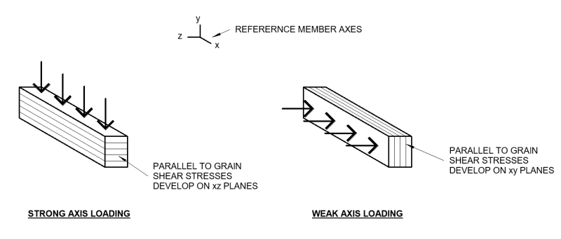
If you refer to the diagram below, I'm showing example surfaces where I think the shear stress parallel to grain is developing on the member under both loading cases. Does the fact that one happens on xy planes and one on xz planes help anything or are those parallel to grain shear stresses still additive?

To my eyes they aren't additive per se, but they do combine (perhaps in an additive sense) at the exact center of the member, which is a line along the length of the member..... I hesitate to dismiss this as "it's so esoteric it probably never happens in reality" but it's a bit tempting. What are the stresses we are dealing with? I mean if we come up with a (novel?) stress check that doesn't apply and the section passes, well, it sounds safe, if we come up with a stress check that's in the code, that's at least orbiting the standard of care, if not hitting it.
Where's the OP, what kind of stress range are we dealing with, is the intended section approaching failure due to shear stress in either plane without considering combination?
Mike Mike - I suppose so, yes, sand heap for torsion. I had a pretty involved design class in grad school, tackled multi-cellular torsion and warping torsion and all that. Had a lot of aerospace majors in it. I just like sand heap because it's fairly easy to visualize.
Regards,
Brian
- Thread starter
- #26
I don't have any exact stress ranges at the moment. This question came from a fellow engineer who was wondering if they should check combined shear, and I didn't have a good response as to why they should or should not. We looked at the design programs we have access to including Enercalc, Risa, and Forte. They all appear to check shear for each direction individually with no combined shear check. I assumed there was a documented reason all three of these programs have landed on that approach, but it sounds like there may not be. I may reach out to one of them to see why they coded it in that way in their programs.
MJC6125 - your image depicts my number and one and number two points from above perfectly. Depending upon how the log was sawn (quarter, rift, rift and quarter, plain) and where the stick came from in the log, you could have grain at a number of angles to the axes of the member. The worst case for single axis bending are the two you show (though the weak axis case is pretty rare for most commercially milled lumber.)
My point three needs a slight revision - 45 degrees isn't the case of concern. It's the angle that corresponds to the peak combination of the two stresses. It's only 45 degrees if the shear stress from both are equal. But that doesn't change anything - the math is still right. Just makes the description make sense!
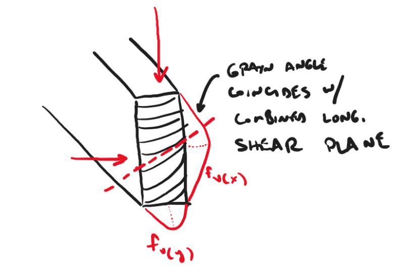
My point three needs a slight revision - 45 degrees isn't the case of concern. It's the angle that corresponds to the peak combination of the two stresses. It's only 45 degrees if the shear stress from both are equal. But that doesn't change anything - the math is still right. Just makes the description make sense!

Also, you're not likely to get much from the software companies. There is no codified check for this in the NDS. Apparently not in Canadian or Eurocodes yet either. The software companies will not introduce code checks that don't exist. To put my sea lawyer hat on for a minute, I'd say they probably have to walk a pretty tight line as it is (despite the EULA stating that the user is solely responsible for the output) as a gross error could probably still land them in hot water with a court. So anything that steps out of the realm of what is actually in the code for a code check is probably not going to happen. Josh can speak more to this if he's around, though, as he's spent a good chunk of his career at RISA and now CSI.
I don't use EnerCalc for anything. Besides showing people how they used it wrong.
I think the two shears only coincide on a point in the center of the cross section. If that section "fails" you develop a kind of diamond shaped area which is larger than the point and it stabilizes. It would also only occur where the two stresses are maximum, so it's over a limited length on the cross section. Steel gets more into combined stresses, I'd be tempted to look at the AISC spec and see if they have anything about combined shear stresses from biaxial bending, but you're dealing with a ductile material there, so if you don't find anything that's maybe not "proof" there isn't a potential overstress. The old ASCE LRFD for wood construction might be worth a scan as well.
I think the two shears only coincide on a point in the center of the cross section. If that section "fails" you develop a kind of diamond shaped area which is larger than the point and it stabilizes. It would also only occur where the two stresses are maximum, so it's over a limited length on the cross section. Steel gets more into combined stresses, I'd be tempted to look at the AISC spec and see if they have anything about combined shear stresses from biaxial bending, but you're dealing with a ductile material there, so if you don't find anything that's maybe not "proof" there isn't a potential overstress. The old ASCE LRFD for wood construction might be worth a scan as well.
Brian, not sure I agree on the diamond failure mechanism. how does the beam know it's being loaded along 2 axes?
phameng, not sure I follow your sketch, isn't max shear at center?
this sketch shows what I think would be the most precise way to calculate your demand. as far as what code addition I would propose, some variation on summing shears was suggested by like fifteen thousand people above and I think that would be a fine approximation.
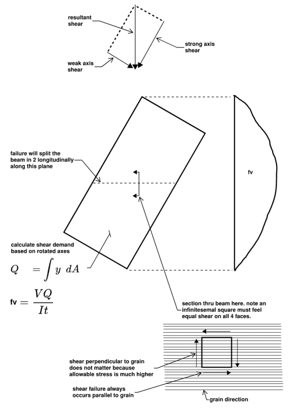

Mike Mike - you're right. I had it correct the first time. I put the good one back. I forgot what Q meant, apparently.
I think it's important to note that the failure will occur on that plane only if it coincides with the plane of the grain at the same point. The likelihood of that happening is probably even less than single axle shear failure plane coinciding with the grain (which is actually pretty common in quarter sawn lumber bent about its major axis), leading to very infrequent failures and an assumption that it can be ignored.
I think it's important to note that the failure will occur on that plane only if it coincides with the plane of the grain at the same point. The likelihood of that happening is probably even less than single axle shear failure plane coinciding with the grain (which is actually pretty common in quarter sawn lumber bent about its major axis), leading to very infrequent failures and an assumption that it can be ignored.
This is an interesting discussion and something I've pondered before but never really investigated further until now.
In general, I agree with Mike Mike's method above.
I think the most theoretically correct approach would be:
[ol 1]
[li]For a beam in biaxial bending with moments Mx and My about the beam's x and y (strong and weak) axes, find the angle of the neutral axis which results in moments having the same ratio as Mx and My, or which has the same resultant angle as the resultant moment Mxy. For example if Mx and My both happened to be equal, then the resultant moment, Mxy = 1.414*Mx and the angle of Mxy is 45 degrees. Be aware that this angle is most likely not equal to the angle of the neutral axis. In the case that the section is square (double symmetric section) it will be equal, but for other cases, like a slender section (2x8 for ex.) it won't.[/li]
[li]Next, given the neutral axis angle found above, solve for the max shear stress. This stress occurs at the neutral axis (mid-depth of the member). This can be solved using the equation: fv = VQ/Ib. The values Q and I need to be solved accounting for the neutral axis angle.[/li]
[/ol]
I investigated both a 2x8 and 8x8 beam in biaxial bending and shear:
[URL unfurl="true"]https://res.cloudinary.com/engineering-com/image/upload/v1699550010/tips/Biaxial_Bending_and_Shear_Investigation_-_2x8_and_8x8_-_2023-11-09_sxf03s.pdf[/url]
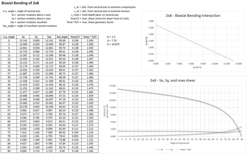
To attempt to answer the OP's original question:
Suppose you were to load a 2x8 beam equally about both x and y axes, resulting in moments, Mx and My, of the same magnitude with the resultant moment, Mxy, at a 45 degree angle. Since the moments are equal, the section moduli, Sx and Sy, are also equal. From the 2x8 graph above, the point where Sx and Sy are equal (and intersect) is roughly at a neutral axis angle of 87 degrees (note that this is not at 45 degrees due to the slender section). Now, if the corresponding shear forces, Vx and Vy also happened to be equal, then the resultant shear force, Vxy, would be 1.414Vx. If you were to look at each shear force independently, you would find (see the chart) that fx_max = 0.138Vx and fy_max = 0.138Vx. You would also find that fxy_max = 0.132(1.414Vx) = 0.187Vx. So, in this particular case, the resultant shear force, Vxy, produces a greater shear stress than the individual components of that force, Vx and Vy.
Perhaps the codes have overlooked this. Although, I think a slender member (like a 2x8) is unlikely to be loaded equally in both the strong and weak directions anyway, and even if it was, it would likely fail in bending first. There probably aren't many likely scenarios where the shear failure would control over a bending failure. Perhaps a large concentrated load applied near a support would be one.
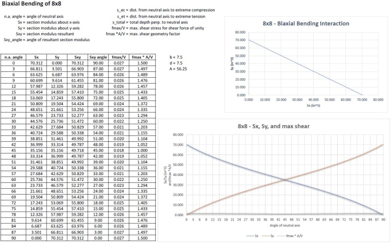
For the 8x8 beam above, it's interesting to note that if the same loading scenario is investigated as for the 2x8, it's found that the resultant shear force, Vxy, does not produce a greater shear stress than the individual components of that force, Vx and Vy. The difference here is that the 8x8 section is not slender, and in fact, at a 45 degree angle, the max shear stress is only 2/3 of the max in either of the orthogonal directions.
It can be observed that for a rectangular section, with width b and depth d:
[ol 1]
[li]If the neutral axis is oriented perpendicular or parallel to the sides, fmax = 1.5 * V / bd[/li]
[li]If the neutral axis is oriented passing through the diagonal, fmax = 1.0 * V / bd[/li]
[/ol]
In the graphs above, at the angles where the neutral axis passes through the member diagonal, the term that I refer to as the geometry/shape factor (fmax*A/V) is equal to 1.
Finally, as a conservative approach, I think it's reasonable to calculate the resultant shear force, Vxy, from the individual components, Vx and Vy, and then, assuming a rectangular section, calculate the max. shear stress as fmax = 1.5 * V / bd. As discussed above, using this approach could be conservative by 50 percent.
In general, I agree with Mike Mike's method above.
I think the most theoretically correct approach would be:
[ol 1]
[li]For a beam in biaxial bending with moments Mx and My about the beam's x and y (strong and weak) axes, find the angle of the neutral axis which results in moments having the same ratio as Mx and My, or which has the same resultant angle as the resultant moment Mxy. For example if Mx and My both happened to be equal, then the resultant moment, Mxy = 1.414*Mx and the angle of Mxy is 45 degrees. Be aware that this angle is most likely not equal to the angle of the neutral axis. In the case that the section is square (double symmetric section) it will be equal, but for other cases, like a slender section (2x8 for ex.) it won't.[/li]
[li]Next, given the neutral axis angle found above, solve for the max shear stress. This stress occurs at the neutral axis (mid-depth of the member). This can be solved using the equation: fv = VQ/Ib. The values Q and I need to be solved accounting for the neutral axis angle.[/li]
[/ol]
I investigated both a 2x8 and 8x8 beam in biaxial bending and shear:
[URL unfurl="true"]https://res.cloudinary.com/engineering-com/image/upload/v1699550010/tips/Biaxial_Bending_and_Shear_Investigation_-_2x8_and_8x8_-_2023-11-09_sxf03s.pdf[/url]

To attempt to answer the OP's original question:
Suppose you were to load a 2x8 beam equally about both x and y axes, resulting in moments, Mx and My, of the same magnitude with the resultant moment, Mxy, at a 45 degree angle. Since the moments are equal, the section moduli, Sx and Sy, are also equal. From the 2x8 graph above, the point where Sx and Sy are equal (and intersect) is roughly at a neutral axis angle of 87 degrees (note that this is not at 45 degrees due to the slender section). Now, if the corresponding shear forces, Vx and Vy also happened to be equal, then the resultant shear force, Vxy, would be 1.414Vx. If you were to look at each shear force independently, you would find (see the chart) that fx_max = 0.138Vx and fy_max = 0.138Vx. You would also find that fxy_max = 0.132(1.414Vx) = 0.187Vx. So, in this particular case, the resultant shear force, Vxy, produces a greater shear stress than the individual components of that force, Vx and Vy.
Perhaps the codes have overlooked this. Although, I think a slender member (like a 2x8) is unlikely to be loaded equally in both the strong and weak directions anyway, and even if it was, it would likely fail in bending first. There probably aren't many likely scenarios where the shear failure would control over a bending failure. Perhaps a large concentrated load applied near a support would be one.

For the 8x8 beam above, it's interesting to note that if the same loading scenario is investigated as for the 2x8, it's found that the resultant shear force, Vxy, does not produce a greater shear stress than the individual components of that force, Vx and Vy. The difference here is that the 8x8 section is not slender, and in fact, at a 45 degree angle, the max shear stress is only 2/3 of the max in either of the orthogonal directions.
It can be observed that for a rectangular section, with width b and depth d:
[ol 1]
[li]If the neutral axis is oriented perpendicular or parallel to the sides, fmax = 1.5 * V / bd[/li]
[li]If the neutral axis is oriented passing through the diagonal, fmax = 1.0 * V / bd[/li]
[/ol]
In the graphs above, at the angles where the neutral axis passes through the member diagonal, the term that I refer to as the geometry/shape factor (fmax*A/V) is equal to 1.
Finally, as a conservative approach, I think it's reasonable to calculate the resultant shear force, Vxy, from the individual components, Vx and Vy, and then, assuming a rectangular section, calculate the max. shear stress as fmax = 1.5 * V / bd. As discussed above, using this approach could be conservative by 50 percent.
-
1
- #33
There is also a practical consideration here. We could sharpen our pencils to the nth degree with complex theoretical analysis methods. But the end of the day, we will still be comparing those applied stresses to allowable stresses that have been derived by statistical methods for natural materials that are graded by humans and that have natural imperfections.
The allowable stresses are based on the code prescription that they will be compared with 1.5 * V / A. It's all an attempt to account for shear stress distribution in a non-isotropic material. It's an educated best guess at quantifying something that is hard to quantify. Fortunately, the current code provisions and allowable values appear to have been serving the purpose of protecting life safety pretty well. Can't think of the last time I heard of a catastrophic failure in shear in dimension lumber.
This isn't meant to imply that we shouldn't understand the behavior of the members we're designing. But it is meant to remind us that ultimately we are dealing with dead cells here.
Director of Engineering
ENERCALC, LLC
Web:
Eng man I just ran through your numbers and I agree on all points. I tried going through similar calcs for a concrete column biaxial bending capacity spreadsheet last year, which actually would have useful, everyday applications in my design work, but I gave up half way through because it was too complicated and I got swamped with real work. If I had to do it again I would guess the neutral axis iteratively instead of calculating it analytically.
Conrad, I agree we don't need to get this deep into the dead cells. We are here because we enjoy getting this deep into the dead cells.
Conrad, I agree we don't need to get this deep into the dead cells. We are here because we enjoy getting this deep into the dead cells.
- Status
- Not open for further replies.
Similar threads
- Replies
- 14
- Views
- 9K
- Locked
- Question
- Replies
- 8
- Views
- 1K
- Locked
- Question
- Replies
- 4
- Views
- 3K
- Replies
- 19
- Views
- 25K
- Replies
- 6
- Views
- 12K
