Eng-Tips is the largest engineering community on the Internet

Intelligent Work Forums for Engineering Professionals

Shear Flow at Neutral Axis 2

Status
Not open for further replies.

Aytacoglu

Civil/Environmental
Dec 4, 2023
33
0
0
GB
Hi All,

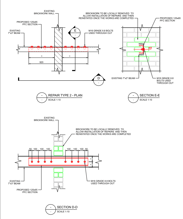
I have a problem where I want to calculate the shear flow in a built up beam where an existing beam will be strengthened by connecting another section to it (in this case the 7"x3" channel will be strengthened by connecting 125x65mm PFC section). See the figure below.

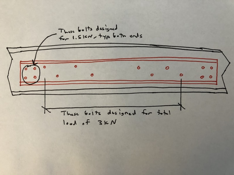
The proposal is to connect the 125x65 PFC to 7"x3" channel by using 1no. bolt at the middle (at neutral axis).

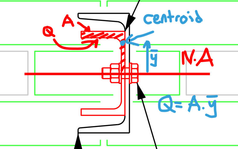
My question is, in order to carry out the shear flow calculation, we have to consider the connected section (125x75PFC) above the neutral axis. Hence the area to be calculated will be the half the area of the 125x65 section. The first moment of area then will be Q = A.y where y is going to be the distance from the neutral axis to the centroid of the half the 125x65 section (see in the figure below). In this case, do we calculate the shear flow like this, than compare it to the capacity of the bolt and work out how many bolts I need at what spacing? Or, since the bolt is connected at the neutral axis, the shear flow calculation has to be carried out at that location, where the Q will come out to be 0 due to the fact that distance from the neutral axis is 0?

Or it doesn't matter whether the bolt is connected (whether it's at the neutral axis or slightly above neutral axis)?

It would be great if someone can provide some clarifications on this problem.
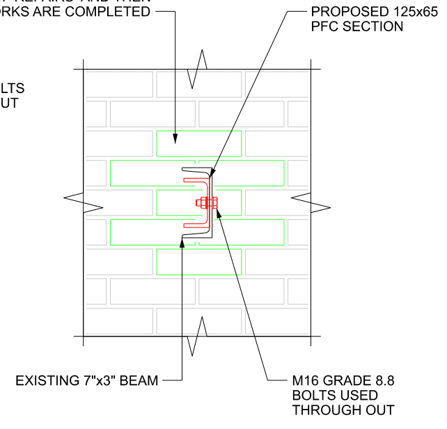
Section_1_zzrdtd.png


Section_2_hqbgzb.png
 
Replies continue below

Recommended for you

I doubt that is even worth calculating.

The total shear is likely to be less than the capacity of a single M16 8.8 bolt unless the member is very short. I'd likely just provide a minimum of 4 bolts at centres of ~750mm and make sure that the end bolts have sufficient capacity for the full transfer of shear.
 
Assuming the beam will be loaded vertically, I would not calculate shear flow at all. Rather, I would determine how much vertical load needs to be resisted by the 125x65mm PFC section, and then I would design a connection to transfer that vertical load between the two pieces. Also, I would stagger the bolts slightly as opposed to having every bolt on the neutral axis.

At the ends of the new piece, assuming they don't extend all the way to supports, I would design a connection to transfer the full shear force back into the existing piece (as mentioned by human909).
 
I don't disagree with human909 or Eng16080. But to answer your question specifically, the shear flow is zero. Your y value is zero. You're looking at this wrong, the Q value isn't based on the portion of the smaller channel above the fastener, you look at how the entire section is combined with the larger channel. Since the neutral axis is aligned in each channel the shear flow is zero. The sections will share the vertical load in proportion to their bending stiffness, and the fasteners will need to transfer the smaller channel's share of the load - this is what human909 or Eng16080 are alluding to.
 
@human909 & @Eng16080 , thank you so much for your input.

@Eng16080, when you say "I would determine how much vertical load needs to be resisted by the 125x65mm PFC" can you elaborate on that a bit? I have attached another figure below to show the connection detail on the elevation as well.

My approach to this was to provide the repair section and calculate the shear flow so that I am sure that the both sections will act compositely. After that, I would calculate the enhanced section modulus for the composite section, and check this with the applied maximum moment and shear. I though the bolts are there to only transfer the shear flow and then the sections will act as if they are one section.

Could you please let me know if you agree with this approach or you think there is something fundamentally wrong? Because in my perspective, this is not going to be like a Splice Connection design where we have to carry out a lot of design checks for the connection itself.

Section_3_faq1p4.png
 
@CANPRO Ah I see your point. But just to understand, when you say the sections will share the vertical load in proportion to their bending stiffness, how is this calculated? Is it the moment of inertia ratio between two sections and just sharing it accordingly? i.e. if the moment of inertia of the bigger section is 2x bigger than the small one, it will carry double the loading applied (9kN applied, 3kN will be carried by small section and 6kN is carried by the bigger section?)

I would appreciate clarifications. Apologies if my questions are a bit silly, as I am not really familiar with this kind of concept and am learning!

Thanks,
 
Your logic is correct. To calculate this, the trick is to think about how these two channels will deflect. The fasteners are going to force equal deflection. You can setup your deflection equations for each channel based on the proportion of the load they are taking (call that P1 and P2, with P1 + P2 = Ptotal), then set your equations equal to each other. You can then solve directly for P1 or P2 in terms of the bending stiffness of the channels.
 
I agree with the comments above.

I would probably look at it like this: you want the new section to support 3kN, which I'll assume is spread out over the length of the new section. So, you have a distributed load of 3kN/length. I would add bolts along the length which can resist this load. Then at the ends, I would have more bolts to transfer 1.5kN back into the existing piece. I don't know how many bolts this will actually require, but I'd expect a layout something like this:
New_Channel_Bolted_to_Existing_v7yr3d.jpg
 
Status
Not open for further replies.
Back
Top