Continue to Site

Eng-Tips is the largest engineering community on the Internet

Intelligent Work Forums for Engineering Professionals

  • Congratulations waross on being selected by the Eng-Tips community for having the most helpful posts in the forums last week. Way to Go!

Shear Flow of Components with Same Neutral Axis 3

Status
Not open for further replies.

Johns20188

Structural
Jan 26, 2015
14
I've been keeping up with the thread below:
There's a lot of great discussion regarding shear flow of members that share the same Neutral Axis. From the thread responses, it seems that there is no shear flow between the members that share a neutral axis.

I understand there's no shear flow for situations like a flitch beam where load is applied to all components and all components are supported independently at the ends.
I've seen a situation where there was a simply supported wood beam that was damaged at midspan. To add strength to the beam, the engineer sistered on two 2x's, one on each side of the beam, bolted. However, the 2x's did not extend all the way to the supports. Also, the load was applied only to the beam, not the sistered 2x's. The members shared the same Neutral axis. So in this situation, is there still no shear flow? How does load get transfered to the 2xs? How do we insure that the 2xs will add strength rather than just add dead load to the main beam? Right now I'm thinking you can't just transfer vertical shear through the bolts to the 2xs because they're not supported independently at the ends.

Thanks in advance for your time.
 
Replies continue below

Recommended for you

A) In all three cases, two of the three vertical plates could be disconnected from the flanges and, instead, be connected to the assembly with just a centroidal line of bolts transferring only vertical shear and, still, all components of the cross section would share a common strain profile.

B) Because of (A), in all three cases, only one of the three webs requires a VQ/IT, shear flow connection in order to force the flanges into sharing a common strain profile with the webs and, thus, behaving compositely.

C) In all three cases, where redundant connections are made between flanges and webs, the associated, redundant webs will share the VQ/IT, horizomtal shear demand that forces the flanges to behave compositely with the rest of the assembly.

D) In all three cases, applying horizontal shears to the redundant web to flange connections would be a more efficient way to force the associated webs to behave compositely because most setups relying on only vertical shear transfer will require transverse flange bending, or something akin to it, to force the redundant webs to travel in unison with the rest of the section.
 
retired13 said:
Yet the picture is getting murkier when a vertical bar is placed in the middle. Because shear flow in the vertical bar will start from zero at top, then gradually increase due to increase in area, thus at the level of junction with the channel

Are you talking about making a section like steveh49 posted? I think you need to re-read what wrote. To quote again "Because shear flow in the vertical bar will start from zero at top" - and this is where it connects to the channel correct? Where there is zero shear flow?


retired13 said:
I suspect the tip of the channel, upon welding, will feel the same stress. and the shear flow is simply taken as the area at the level of the top flange times distance to the NA, and divide by 2, for 2 faces in sharing the stress

Why do you feel that way? Adding a 3rd vertical bar doesn't change the shear flow at the tip of the channel flange. The concept is still the exact same as what is in the link that you posted. I believe you're basically comparing points A/B (or C/D or E/F) in steveh49's sketch. KootK answered this, shear flow doesn't existing at A, C, or E (because you're looking at the junction of a component of the section that shares a common neutral axis with the combined section) and there is shear flow at B, D, and F (because you're looking at the junction of a component that does not share a common neutral axis with the combined section).


KootK said:
C) In all three cases, where redundant connections are made between flanges and webs, the associated, redundant webs will share the VQ/IT, horizomtal shear demand that forces the flanges to behave compositely with the rest of the assembly.


CANPRO said:
KootK answered this, shear flow doesn't existing at A, C, or E (because you're looking at the junction of a component of the section that shares a common neutral axis with the combined section)


Are these statements the same?
 
steveh49 said:
Are these statements the same

No, KootK is referencing points B, D, and F in that statement. In your 3 examples there is never any shear flow at points A, C, and E, and there is always shear flow at points B, D, and F (unless you leave two plates unconnected as proposed by KootK).
 
I believe there to be a subtle difference between my understanding and CANPRO's understanding on this. In steveh49's sketches, I believe that there will indeed be shear flow at (A,C,E). It's just that those shear flows are redundant from the perspective of enforcing a common strain profile upon the assembly. We could forgo those connections and still create composite behaviour but, once in place, I expect that they will draw horizontal shear

I can't upload sketches at present. If somebody does the shear flow diagram on steveh49's three web thing, I suspect that would clear things up. The zero shear locations should be in the flanges, somewhere between the webs I think.
 
I agree with KootK. In the other topic, there were statements that the shear flow is not necessary. However, if you don't size the welds for the elastic solution, you'll yield the welds, potnetially at low load. I prefer to avoid that.
 
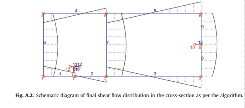
Here's the shear flow distribution for a two-cell section from the literature.

twin_cell_shear_flow_mn9rwk.gif
 
Well, it turns out that shear flow in multi-cell cross-sections is too complex for a simple VQ/IT and too complex for this simple engineer.

I believe that the simple VQ/IT fails us here. You can apply this equation where the webs meet the flange and it is clear that flanges are "supplied with bending stress" from the three webs, so the point of no shear flow must be between the two webs - I get that now. But if you were to apply the simple VQ/IT formula at point A (ref steveh49's sketch) or anywhere else along the flanges, the value Q comes from the bit of C-shape left over and is equal to zero, which is contrary to what is happening in reality.

See this link which seems to provide the theoretical background to steveh49's last post. There is an identical shear flow diagram on page 36 of the PDF. I don't have it in me right now (or probably ever unless I have to) to sort through the math and see where the simple VQ/IT becomes incorrect.

Apologies to anyone I may have offended in this or the previous thread. It seems I was wrong about the original condition with the 36" vertical plate and two C15 channels - that forms a multi-cell closed section and does in fact develop shear flow in the welds.
 
CANPRO, if the system has some ductility, you can cut the section into single-web elements that each have their centroid at the same level as the composite section. Equal flange width if the thicknesses don't vary. It's not correct but close enough, hence the ductility proviso. Probably close enough for the safety factor to avoid yield at service load.

One method to do it properly is to cut each cell once so there are no closed cells. Start from zero shear flow at the cut, work out how the result is wrong (not in equilibrium), apply equal-opposite shear flow to restore equilibrium. I wouldn't do this personally; I'd get a keen young engineer to do the hard yards if this were ever necessary.

Edit: Canpro's doc says you have to use compatibility to work out the shear flow, not equilibrium. Even worse. Definitely a task to delegate.
 
steveh49 said:
you have to use compatibility to work out the shear flow, not equilibrium

Yup, thats where I get off this crazy train. Good talk team.

To quote KootK from the original thread:

KootK said:
Go forth and be profitable my friend. Expend your serious mental horsepower on some problems more worthy of it.

For me, it is certainly that time.
 
For what it's worth, I leaned a few things of value to me during this process. That usually only happens when somebody has the moxie to fly a little to close to the sun.
 
Status
Not open for further replies.

Part and Inventory Search

Sponsor