Continue to Site

Eng-Tips is the largest engineering community on the Internet

Intelligent Work Forums for Engineering Professionals

  • Congratulations KootK on being selected by the Eng-Tips community for having the most helpful posts in the forums last week. Way to Go!

Shear Flow vs M/d

Status
Not open for further replies.

mikeCTE

Structural
Feb 21, 2014
41
I will fully admit to being rusty on the subject since I don't deal with it (hardly ever) and it's been a long time since school...

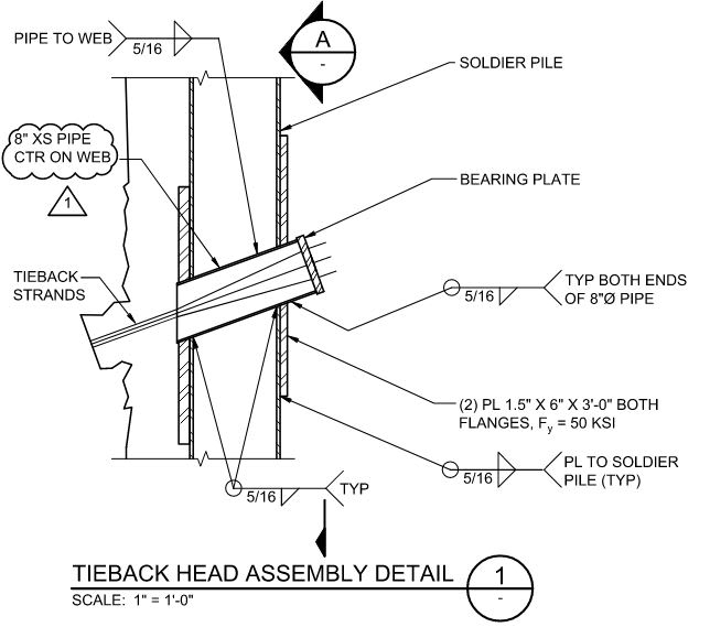
If I have a soldier pile (W-beam) with a hole in it for a tieback, and I want to reinforce the flanges to make up for the loss of the section at the hole, I would intuitively solve for a flange force. To do this, I would use Moment / Depth (measured to the weld line) and then size the reinforcing plate and the weld to resist that flange force.

However, we have received comments from the AHJ that our plates are too long and they recommend using a shear flow equation like the one shown in the link below:

Which approach would you use and why? And, what am I missing in my logic of using M / d?

For the sake of the detail, I would assume you get no axial resistance from the web as it's been scarfed out to insert a pipe.
Capture_hbmqgz.jpg
 
Replies continue below

Recommended for you

For dealing with cross sectional capacity as governed by basic flexural stress, I feel that:

1) M/d is correct and;

2) I don't really see how a shear flow analysis would help this since, if done properly, it would reduce to the same thing with all of flexural stresses being corralled into passing through the flanges.

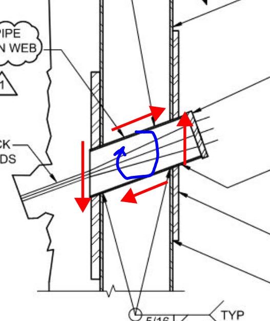
3) As an aside, to the extent that there's a shear flow thing to be considered, it's probably in how that bit of tube is stabilized rotationally, as shown below.

Are the reinforcing plates just rectangular bars or are they fitted around the sleeve?

c01_schhcu.jpg
 
mikeCTE said:
However, we have received comments from the AHJ that our plates are too long..

Curious: why does the AHJ find longer plates ojbectionable?
 
Also, how wide are the flanges on these solider piles? I'm wondering if some of the stress can't remain in the flanges and avoid being passed through the reinforcing and associated welds.
 
KootK,
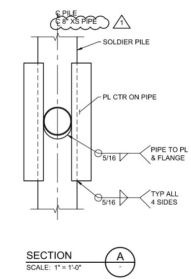
The splice plates are typically around the sleeve. we try to use 14" flange base width or larger because the splice plates need to be at least 12" wide to fit the 8" pipe and still have some plate area that adds to Sx of the built up cross section.

image_wuz0pb.png
 
Section A would aid understanding.

I imagine that a shear flow calc would give smaller weld requirement than what you've done. Assuming the doubler plates don't extend to the point of contraflexure, the shear flow calc will assume a beneficial non-zero stress at the end of the plates (M*y/I) which would reduce the required weld capacity. The reality is this is a 'disturbed' region where Bernoulli theory doesn't apply.

I find the pipe acting as the web more intriguing, but assume it's fine provided the wall thickness is similar to the web thickness.
 
Some additional thoughts:

1) Given that one loses 100% of the web across the pipe, I'm inclined to view this more as a connection that as "reinforcement". Basically a moment connection between the upper and lower sections of beam. And, of course, in the world of steel moment connections, the precedent is to treat it as mikeCTE has proposed.

2) Even if one were to go the reinforcement route, normal practice in that area usually includes:

a) "Developing" the reinforcing beyond the theoretical cutoff point (Mc/I) and;

b) Using a connection length about 1.5 X the plate width for shear lag etc.

With those things in play, I don't see the plate getting a whole lot shorter than it originally was (about 16" extension beyond the pipe).

@rllo: thank you for the helpful, clarifying sketches.

 
All:

Thanks for the responses. I didn't get email notifications, hence my delay in responding.

The reinforcing flange plates are two individual strips of plate. We do not have a hole cut out in the middle since it doesn't really benefit us to do so, and actually makes the length longer because you don't have as much weld length available with the single plate + hole option.

I do not know why the AHJ takes issues with this. I am receiving something like 4th or 5th-hand information (don't ask me about the processes; I'm not in charge of this one and don't plan to interject myself into it). I presume the reasoning is that they are a state DOT and have done this before. However, in looking at their standard plans, there are many things, despite being less than 1 decade old, that are incorrect with their plans.

The pipe that serves as the sleeve and bearing mechanism for the tieback is welded on every surface that it touches. I cannot picture this being unstable. The pipe itself is basically sized for the tieback load. Then, to complete the shear path into the web of the soldier pile, the weld between the web and pipe is sized to transmit required load.

I don't know what the flange width is on this particular project, but I assume it's 10" minimum, but more likely 12" or higher. The maximum moment in the pile always occurs at the splice location due to the tieback (i.e. boundary support). Thus, the overall pile size is based on this max moment, and there is little reserve capacity in the flanges, hence the need for splice plates.


Capture_zi5me0.jpg
 
It seems like there are two different methodologies. The DOT said to consider the pile section with a hole reinforced by cover plates by using shear flow and the OP is designing neglecting the pile section and considering the cover plates only. What is the difference in the results? It might be fairly small.
 
Status
Not open for further replies.

Part and Inventory Search

Sponsor