Continue to Site

Eng-Tips is the largest engineering community on the Internet

Intelligent Work Forums for Engineering Professionals

  • Congratulations KootK on being selected by the Eng-Tips community for having the most helpful posts in the forums last week. Way to Go!

Shear Flow with a Uniform Moment 2

Status
Not open for further replies.

wadavis

Structural
Jan 14, 2013
60
If a composite member has a uniform moment along it's length (dM=0), how do I calculate the required shear flow capacity between it's bonded components for composite behavior?

I understand this is a little academic for these boards, but separating the theory conversation from the application should keep the discussion on topic.

Structural, Alberta
 
Replies continue below

Recommended for you

wadavis said:
I understand this is a little academic for these boards
I don't think that's a thing... [pipe]

Interesting question... Although it feels intuitive to think there should be some longitudinal stress to resolve, I think the answer is as the formula would suggest - zero.
 
Doesn't it all depend on the shear across that section of member where the constant moment occurs?

If you have a simple span member with two concentrated loads at the 1/3 points, the moment is constant between the two loads but the shear varies from load to load in a "bowtie" pattern.

q = VQ/I right? So per the V there would be some type of shear that would have to be some bonding between the components.

If you have a member with two concentrated end moments - perhaps no shear along the member and no bonding required?

Check out Eng-Tips Forum's Policies here:
faq731-376
 
I don't think the shear will look like a bowtie without a uniform force, if the two loads are equal it's actually zero for the portion of the beam between them. From a purely academic point of view, if you have way of applying moment with no shear, all you are doing is applying axial forces to the two halves of the member and the connection between the two is irrelevant. However, in a real world case, I don't know how you can apply only moment, and our beam buckling formulas all rely on the tension and compression regions being tied together such that buckling is restricted, and needs to occur laterally and torsionally.
 
I'm confused, wouldn't shear flow be VQ/I? Wouldn't the support reactions introduce shear due to the applied moment. Seems like you would use this shear to design for composite connection.
 
BowlingDanish said:
I think the answer is as the formula would suggest - zero.

I think this too.

I believe that the trick to this is recognizing that, at the ends of the member, the moment has to be applied in such a way that it instantaneously creates a strain profile common to both materials. That's a pretty tall order for any real world loading situation other than where the "member" is really just a segment of consideration within a larger member. Especially so if one or more of the materials is a thing that cracks and creeps and generally behaves in a complex, non-linear manner.

Where the instantaneous development of a common strain profile is not realistic, shear flow capacity would need to be provided needed near the ends of the member to bring things in line, so to speak. In a lot of practical situations, I think that it would be prudent and conservative to assume that the moment originates in one of the materials and has to migrate to the other via localized shear flow.


I like to debate structural engineering theory -- a lot. If I challenge you on something, know that I'm doing so because I respect your opinion enough to either change it or adopt it.
 
OP said:
I understand this is a little academic for these boards

Pfft. Get the attention of the right cadre here and we'll bury you alive in esoteric voodoo.

I like to debate structural engineering theory -- a lot. If I challenge you on something, know that I'm doing so because I respect your opinion enough to either change it or adopt it.
 
Maybe I am misunderstanding but how do you have uniform moment without shear introduced by your reactions? If there are no reactions doesn't the object just spin? In this case I don't think you would need a tie between the elements but it also wouldn't be statically stable.
 
jd said:
Maybe I am misunderstanding but how do you have uniform moment without shear introduced by your reactions?

Opposing end moments. It's a rare thing but not unheard of. The central segment of JAE's 1/3 point loaded beam is a good example. A column assumed to be loaded, and supported, eccentrically by the same amount is another.

I like to debate structural engineering theory -- a lot. If I challenge you on something, know that I'm doing so because I respect your opinion enough to either change it or adopt it.
 
Nevermind. I realize I'm wrong. Sounds like application would be providing a moment at the two ends of the member (similar to grabbing a board by the edges and bending it). Interesting question.
 
So say you stacked 10 1" plates together and bent them vs 1 10" tall plate. Would they behavior fundamentally different? Typical logic would be yes the 10" plate would have much larger moment of inertia than the individual plates. But maybe in this instance it doesn't matter. Not really sure. Maybe curvatures are restrained and locked to be the same so it doesn't matter? Interesting question.
 
I think I didn't stop to think - with two point loads the shear is zero between the loads.

Check out Eng-Tips Forum's Policies here:
faq731-376
 
jd said:
So say you stacked 10 1" plates together and bent them vs 1 10" tall plate. Would they behavior fundamentally different? Typical logic would be yes the 10" plate would have much larger moment of inertia than the individual plates. But maybe in this instance it doesn't matter. Not really sure. Maybe curvatures are restrained and locked to be the same so it doesn't matter?

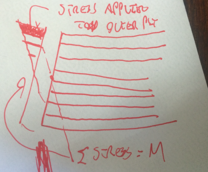
The moments would have to be applied as a bunch of independent, linearly varying axial stresses that, when summed, would simulate the stress and strain profile of a composite member. Like I said, that's a tall order but, if it can be accomplished, there is no VQ/I demand between plies. Really, the end result would be a bunch of disconnected layers with linearly varying, mostly axial loads applied to them such that the aggregate condition would simulate the strain profile of a composite member.

Capture_mmi6cc.png


I like to debate structural engineering theory -- a lot. If I challenge you on something, know that I'm doing so because I respect your opinion enough to either change it or adopt it.
 
In my case I have an eccentric axial load applied to a member, that's where the uniform load without shear is coming from. Although VQ/I = 0, the deflection of that member depends on I, the I is different for a composite member than for a bundle of fibers with no shear flow. So there must be a way to calculate the required cohesion for composite behavior from the moment.

KootK said:
The moments would have to be applied as a bunch of independent, linearly varying axial stresses that, when summed, would simulate the stress and strain profile of a composite member. Like I said, that's a tall order but, if it can be accomplished, there is no VQ/I demand between plies. Really, the end result would be a bunch of disconnected layers with linearly varying, mostly axial loads applied to them such that the aggregate condition would simulate the strain profile of a composite member.

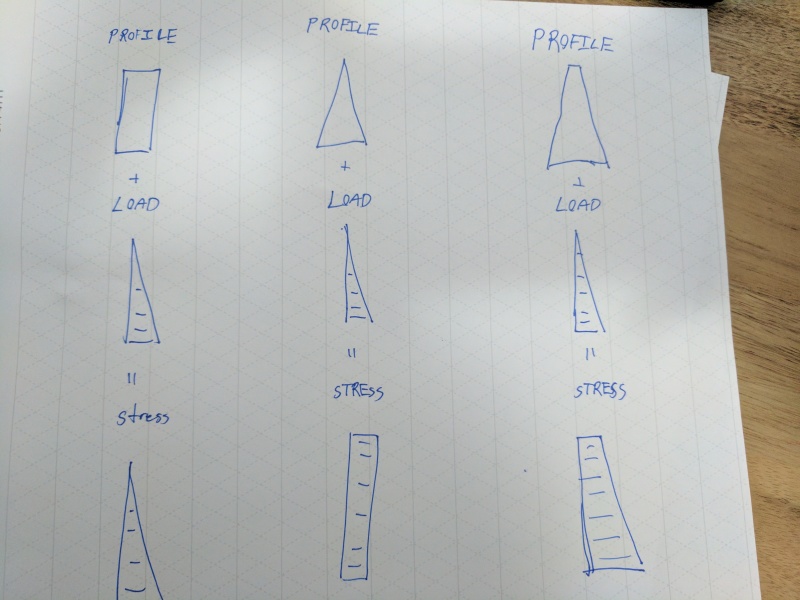
IMG_20170225_151339_nrla97.jpg


So with a symmetrical profile or a profile proportioned to the load shape the local dP/dA = Axial Stress. But with a non-symmetrical member that is not the same shape as the load profile, dP/dA =/= Axial Stress. So some sort of composite behavior is required.

Structural, Alberta
 
wadavis said:
So some sort of composite behavior is required.

I don't believe it is.

Consider this;

- A rigid clamp that matches the member cross-section (any shape) is installed at each end of the beam
- It rotates about a perfect pin at the neutral axis of the member
- By applying a uniform moment at each end without shear, you are effectively dialing in a certain final rotation of the clamps. That rotation is governed by the stiffness of the axial compression and tension of each longitudinal fibre - which doesn't depend on I.

I can't say I understand your sketch though... The 'load' you are applying is not that of a uniform moment?
 
wadavis said:
the I is different for a composite member than for a bundle of fibers with no shear flow.

This statement is only true when shear flow is required. That, of course, is the overwhelming majority of the time. When shear flow is not required, Ix is identical for members with and without laminar shear connection. This recent thread is highly related to your question and may well resolve this for you: Concentric Tube Bending


I like to debate structural engineering theory -- a lot. If I challenge you on something, know that I'm doing so because I respect your opinion enough to either change it or adopt it.
 
That composite behavior vs shear load is what I'm struggling with.

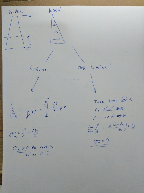
When I apply my eccentric tension to the member (triangle load distribution in the above sketch), convert the eccentric load to a Force and Moment at the centroid, and calculate the stress in the extreme fibers (P/A + My/I); I get a different stress result at any given location than I get when I slice the member and load into small slices and distribute a fraction of the load over the corresponding fraction of the member area.

In a member without laminar connections the method of slicing (dP/dA) should get the same result as any other method but if you calculate the bending stresses as a composite member (P/A + My/I) you get slightly different stresses. See the sketch, I'm afraid my notation is very rust, sorry.
IMG_20170225_175444_pmtcvz.jpg


Sorry about the unclear sketch earlier. The right most diagram is a simplification of my problem, the left and center sketches were my brainstorms on the rigid clamping approach, circumstances where I get the same stress result for shapes with or without laminar connection.

I'm not trying to be stubborn here, just this problem has me doubting.

Structural, Alberta
 
OK... So it's not just a uniform moment at each end - you're also introducing additional axial forces.

My view would be this - based on nothing but intuition;

- Take the same member supported on perfect rotational pins, and supported vertically.
- Take the same rigid clamp and apply your moment, giving you a certain rotation and curvature of member
- Now apply your axial load (its concurrent but meh)
- I would guess that due to the curvature of the member, the axial load you are applying would either try 'straighten' the member (tension) or curve it further due to eccentric load (compression).
- This 'straightening' or 'additional curving' would result in some tangible vertical shear force at the support.
- This shear force is what you would use to calculate the required shear flow

Pure speculation [pipe]

PS - I still dun get your sketch. calculus is beyond me now.
 
I'm still struggling a bit with the thought that the members don't need any connection between layers in this case. I understand the theory and agree without V the equation says it's not necessary, but take the example of a phone book. If you grab it by the ends and twist your wrists it's fairly flexible. Don't you think it would be more rigid if it was a solid piece?
 
I don't believe that the presence of the axial stress changes anything. By negative superposition, you can strip it out and again deal with the uniform moment as before.

jd said:
I'm still struggling a bit with the thought that the members don't need any connection between layers in this case.

Consider the absurdly trivial yet altogether salient analog of an axially loaded member. Say, 2-2x6 that you'd like to resist an axial load of 1000 lb compositely. Don't sweat buckling or the moments due to eccentricity. Neither is germane to the example. You've got three possibilities:

1) Put all 1000 lb on one of the 2x and do not nail the plies. One ply resists, the other does not, the axial strain profiles of the two sticks do not match, and you have the analog of the non-composite case.

2) Put all 1000 lb on one of the 2x and do nail the plies. Load transfers between plies, each ply resists 500 lb, the axial strain profiles of the two stick match, and you have the analog of the composite case where shear transfer between plies is required.

3) Put 500 lb on each of the 2x and do not nail the plies. No load needs to be transferred between plies, each ply resists 500 lb, the axial strain profiles of the two stick match without any interconnection, and you have the analog of the composite case where shear transfer between plies is not required.

The uniform moment example here is very much like #3.


I like to debate structural engineering theory -- a lot. If I challenge you on something, know that I'm doing so because I respect your opinion enough to either change it or adopt it.
 
Status
Not open for further replies.

Part and Inventory Search

Sponsor