Eng-Tips is the largest engineering community on the Internet

Intelligent Work Forums for Engineering Professionals

Shear Flow with a Uniform Moment 2

Status
Not open for further replies.

wadavis

Structural
Jan 14, 2013
60
0
0
CA
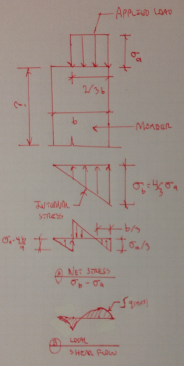
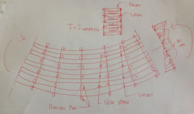
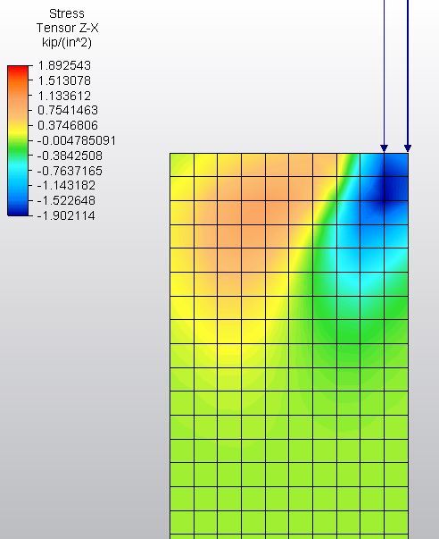
If a composite member has a uniform moment along it's length (dM=0), how do I calculate the required shear flow capacity between it's bonded components for composite behavior?

I understand this is a little academic for these boards, but separating the theory conversation from the application should keep the discussion on topic.

Structural, Alberta
 
Replies continue below

Recommended for you

In the case of the latest sketch by wadavis, in order to act compositely, every horizontal section through the profile has a shear flow wherever the area under the load diagram above or below the section differs from the area under the stress diagram above or below the section. The shear flow is equal to that difference.

BA
 
KootK said:
Where the instantaneous development of a common strain profile is not realistic, shear flow capacity would need to be provided needed near the ends of the member to bring things in line, so to speak.

BAretired said:
every horizontal section through the profile has a shear flow wherever the area under the load diagram above or below the section differs from the area under the stress diagram above or below the section. The shear flow is equal to that difference.

I think that we're probably speaking to the same phenomenon here. I've explored it a bit below for the case of a rectangular section with a load eccentricity of B/6. I think that it's worth noting that this shear would be of a different, and lesser, order of magnitude that one would expect from a true flexural application.

Capture_tjtied.png


I like to debate structural engineering theory -- a lot. If I challenge you on something, know that I'm doing so because I respect your opinion enough to either change it or adopt it.
 
jd said:
But KootK what about the phone book analogy or do you not agree with that analogy?

I agree with the phone book analogy but feel that it is missing an important feature in this instance. Namely, it's missing little axial loads at the end of each page that increase linearly towards the outside edges of the phone book and simulate the linearly varying stress that would normally produce linearly varying strain.

At the end of the day, all you need to make use of composite section properties is for all of the cross section to flex according to a common strain diagram. One way to achieve that is to force them to strain together via shear flow. Another is to load them in such a way that their strains match at the boundaries without the need for shear flow capacity.

I made the sketch below to study your phone book analogy as I see it. The pages are separated by by rolling pins and each page is loaded independently. Not sure if this will clarify things or further confuse them. Let me know if I've made things worse.

Capture_vnvkdx.png


I like to debate structural engineering theory -- a lot. If I challenge you on something, know that I'm doing so because I respect your opinion enough to either change it or adopt it.
 
jd said:
but take the example of a phone book. If you grab it by the ends and twist your wrists it's fairly flexible. Don't you think it would be more rigid if it was a solid piece?

I also believe that three additional things are producing that flexibility:

1) the pages in compression are buckling.

2) the pages are not held together vertically.

3) your hands are not providing perfect shear slip restraint at the ends to apply the moment as I've described.

Obviously, I've never seen you bend a telephone book. You might be the hulk and doing an incredible job of it.


I like to debate structural engineering theory -- a lot. If I challenge you on something, know that I'm doing so because I respect your opinion enough to either change it or adopt it.
 
A laminated beam with two concentrated loads placed symmetrically on the span has zero shear between loads and requires no shear resistance between plies. The plies must be adequately fastened to each other to prevent individual plies from buckling under load.

BA
 
The only shear flow required between components under pure bending (ie imaginary) would be what is required to prevent one component from buckling differently than adjacent components. This would be similar to the required longitudinal connections between elements in a built up steel member in AISC.

Keeping our phone book analogy - we'd need to transfer the resultant axial loads due to the end moments for each page - I figure dipping the edges into 1/2" of glue. I can't think of away to keep the compression pages from buckling though.
 
A little late to the party, but back to the case the OP is describing - as long as there is no change in moment/axial force there is no shear flow in the situation you have described. However, the two members need to be connected at the end receiving the eccentric load such that the triangular stress profile develops. What does the connection look like at this end?
 
Wadavis, I think you may be confusing classical shear flow with shear lag. When you load a column eccentrically, in order for the load to "spread out" there needs to be shear between the fibers. This is not your classic VQ/I. To be honest, I'm not sure how you would compute this so for grins I made an FEA model of an eccentrically loaded column. Once the load spread out there was hardly any shear as would be expected when the moment is not changing. Here's a screen shot of the shear distribution. This is a 10" wide column with just the right 1" loaded. It's 100" long. It only took about 11" before the shears went practically speaking to zero.

Capture_uyhbe9.jpg
 
Thanks everyone for the great input. I'm with the phonebook example, as long as there is some way to create even strain where the load is applied (shear flow resistance or rigid clamping) the member wont have a shear flow demand and therefor Ix wont be dependent on it. Bend your phonebook with the spine providing shear flow, then cut a 2" notch out of the spine and try again, should have similar behavior.

Kootk said:
2) Put all 1000 lb on one of the 2x and do nail the plies. Load transfers between plies, each ply resists 500 lb, the axial strain profiles of the two stick match, and you have the analog of the composite case where shear transfer between plies is required.
This member should behave the same if you glue the plies together, or if you just nail the the last 1' of each end together with no shear connections along the center span.

I was barking up the wrong tree with my problem. Looks like my problem is a local shear flow issue as the loading distributes across the member profile, well shown in KootK's vertical load sketch (edit: and in Dozer's FEA). I'm going back to the drawing board: seeing if I can find any literature on the shear load on the connections between atmospheric tank shells of different thicknesses under hydro-static stress.

Structural, Alberta
 
Status
Not open for further replies.
Back
Top