I have a shear friction question. I am involved in a project where the structural engineer specified hollow precast concrete piles. See the attached sketch. This is already built. The connection of the pile to the pile cap is through rebar and poured concrete in the top of the hollow pile. See the sketch. It appears the engineer is counting on friction between the cast in place concrete and the inside surface of the pile. I understand ACI 318 to allow shear friction only if there is rebar across the joint. Since there is no rebar between the CIP concrete and the precast pile, ACI would not allow the use of the shear friction concept. Do you agree?
Navigation
Install the app
How to install the app on iOS
Follow along with the video below to see how to install our site as a web app on your home screen.
Note: This feature may not be available in some browsers.
More options
You are using an out of date browser. It may not display this or other websites correctly.
You should upgrade or use an alternative browser.
You should upgrade or use an alternative browser.
Shear Friction - Cast in Place Concrete & Precast Concrete 2
- Thread starter PEFLWI
- Start date
- Status
- Not open for further replies.
Even if that interface was dead smooth and frictionless, the hollow pile and the infill still have to maintain compatibility in bending. The curvature in the hollow pile will be equal to that of the infill, and so they would behave as though they were composite, even if there is no interface shear generated between them.
I would even take a guess to say that for the frictionless assumption, there would not even be any slip generated between the two parts at their interface, since their centroids are concentric.
For axial forces that obviously wouldn't work, I think you'd need to rely on bearing on the top end of the hollow pile.
-
1
- #4
I disagree with the shear friction assumption requiring rebar crossing the interface. That rebar is primarily to resist outward wedging forces as the joint tries to open. In a pile these outward wedging forces are counteracted by hoop stresses within the pile. The pile does of course need to be sufficiently reinforced to resist this.
- Thread starter
- #5
user277418
Structural
Are uplift forces large enough to uplift the structure?
Is the CIP mandrel done from non-shrinkage concrete? Any cohesion bond?
Is it possible that the uplifting pressure appears unevenly under the pile cap so it introduces rotation of the cap (for example if the cap is large in plan and incorporates many piles)? There might appear some clamping between the CIP mandrel and the PC pile due to the rotation as bugbus has stated. But it is going to be tricky to account it safely.
If the pile is compression pile , ( will not experience tension) check against downward force easy and should not be concern as jayrod12 (Structural) stated . Just check the bearing area of the prestressed hollow pile ,
If the pile may subject to uplift -tension force , the reliable resistance would be friction force developing btw CIP mandrel and interior surface of the pile . The friction based on cohesion would be around 15 psi. The frictional resistance could be increased with roughenning the interior surface of pile , using non-shrink conc. etc..
When ever i see prestressed pile foundation, i remember the Pile foundation Failure in China.
Just saying..
Use it up, wear it out;
Make it do, or do without.
NEW ENGLAND MAXIM
Your thoughts are right, there will be very small surface shear-friction, due to smooth circular surface inside precast pile.
As most here indicated that this joint use for bearing only purposes (No uplift force is allowed)
You indication is correct that shear force only developed (with accountable magnitude) if there is traverse shear links between the two structural members.
As most here indicated that this joint use for bearing only purposes (No uplift force is allowed)
You indication is correct that shear force only developed (with accountable magnitude) if there is traverse shear links between the two structural members.
BridgeEngineer21
Structural
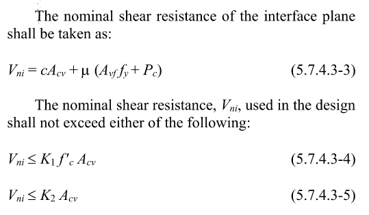
I'm not very familiar with ACI but AASHTO has this equation for interface shear capacity. You can omit the reinforcement term. They do also have a requirement in the previous section for minimum reinforcement crossing the interface, but it is mainly written about girder/slab interfaces. It doesn't say that the interface capacity equation is invalid unless you meet that requirement.
Eurocode 2 has essentially the same equation as AASHTO, and they don't have a minimum interface reinforcement requirement as far as I am aware.

Do you have any cases with the entire pile cap in tension? Or just some individual piles within a larger pile cap?
Eurocode 2 has essentially the same equation as AASHTO, and they don't have a minimum interface reinforcement requirement as far as I am aware.
Do you have any cases with the entire pile cap in tension? Or just some individual piles within a larger pile cap?
user277418
Structural
Tomfh said:I disagree it can’t do uplift. That plug ain’t coming out any time soon.
It’s a common detail too for steel screw piles, which are just a steel tube, as opposed to a rougher concrete pile.
Definitely not a single structure is going to fly to the sky due to uplift. However how severe effect of uplifting on the structure is also depends on the structure itself. Some more prone some less.
user277418
Structural
BridgeEngineer21 said:Eurocode 2 has essentially the same equation
There are a couple of paragraphs in EC2 a bit further after the formula. If the interface is cracked then c*fctd=0. If no external normal force is presented across the interface that can act simultaneously with the shear force then μ*σn=0. Then only reinforcement remains.
The wall thickness of the pile is 7", so how much compression stress do anticipate on the plug?
The tensile question seems similar to the bond between a CIP slab and topping. How the inside of the pile is formed seems important and the shrinkage of the plug itself.
When we have driven steel piles the soil inside the pile can settle quite far down inside the pile (have seen 1/2 pile depth). That will depend on your soil conditions obviously, but unless they install a plug, I would not be surprised if the plug is far deeper than your section. Installing a plug v. extra concrete can be a make work project of little benefit when you consider time and cost.
BridgeEngineer21
Structural
user277418 said:There are a couple of paragraphs in EC2 a bit further after the formula. If the interface is cracked then c*fctd=0. If no external normal force is presented across the interface that can act simultaneously with the shear force then μ*σn=0. Then only reinforcement remains.
Agreed about the normal force term. But for c*fctd, the language is "if the joint can be significantly cracked." I interpret that that if you can prove that service limit state checks are satisfied, then cracking will remain within allowable limits - i.e. not "significantly"
HTURKAK said:If the pile may subject to uplift -tension force , the reliable resistance would be friction force developing btw CIP mandrel and interior surface of the pile . The friction based on cohesion would be around 15 psi.
Hturkak, this resistance is better than I would have guessed. Do you have a reference for 15 psi?
- Thread starter
- #18
user277418:
Yes, there are uplift forces on the piles.
HTURKAK:
Where does the 15 psi of allowable friction come from? Is this a service level capacity or ultimate? Unfortunately, this is already poured. We cannot roughen the precast pile surface.
Tomfh:
There is no horizontal reinforcing in the piles to resist hoop stresses.
Thanks.
PEFLWI said:There is no horizontal reinforcing in the piles to resist hoop stresses.
What reinforcing does the pile have? No ties at all?
-
1
- #20
Dear @ CDLD ,@ PEFLWI
The references for the shear at the interface for cohesion based friction resistance 15 psi are ;
- EC EN 1992 Clause 6.2.5 Shear at the interface between concrete cast at different times, The simplified expression (6.25)
vRdi = c fctd + μσn + ρ fyd μ ≤ 0.5 ν fcd
( In this case 2nd and 3rd terms zero since σn and ρ are zero ) so the expression becomes vRdi = c fctd the cohesion proposed for Very smooth surface a surface cast against steel, plastic or specially prepared wooden moulds) c = 0,025 to 0,10 and fctm for C25 ( common str.) is 2.6 MPa and fctd = 0.7 × fctm/ 1.5=1.2 MPa . and vRdi = c fctd for c=0.1 vRdi = 0.12 MPa . I have attached the EC-2 .( This will not violate copy wrights since law resource )
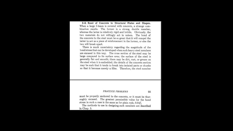
- I looked an old book (Clarence DUNHAM ,THE THEORY OF REINFORCED CONCRETE , 1944 ed.) The allowable bond stress for steel plates , structural shape = 0.04 Fc
- More than 20 yrs ago i have encountered a very similar case and with engineering judgement , i proposed to use 15 psi but the consultant ask test . A few tests conducted at an univerity lab, the scholar proposed upper limit 18 psi .
Use it up, wear it out;
Make it do, or do without.
NEW ENGLAND MAXIM
The references for the shear at the interface for cohesion based friction resistance 15 psi are ;
- EC EN 1992 Clause 6.2.5 Shear at the interface between concrete cast at different times, The simplified expression (6.25)
vRdi = c fctd + μσn + ρ fyd μ ≤ 0.5 ν fcd
( In this case 2nd and 3rd terms zero since σn and ρ are zero ) so the expression becomes vRdi = c fctd the cohesion proposed for Very smooth surface
a surface cast against steel, plastic or specially prepared wooden moulds) c = 0,025 to 0,10 and fctm for C25 ( common str.) is 2.6 MPa and fctd = 0.7 × fctm/ 1.5=1.2 MPa . and vRdi = c fctd for c=0.1 vRdi = 0.12 MPa . I have attached the EC-2 .( This will not violate copy wrights since law resource )- I looked an old book (Clarence DUNHAM ,THE THEORY OF REINFORCED CONCRETE , 1944 ed.) The allowable bond stress for steel plates , structural shape = 0.04 Fc
- More than 20 yrs ago i have encountered a very similar case and with engineering judgement , i proposed to use 15 psi but the consultant ask test . A few tests conducted at an univerity lab, the scholar proposed upper limit 18 psi .
Use it up, wear it out;
Make it do, or do without.
NEW ENGLAND MAXIM
- Status
- Not open for further replies.
Similar threads
- Question
- Replies
- 22
- Views
- 39
- Question
- Replies
- 12
- Views
- 33
- Locked
- Question
- Replies
- 2
- Views
- 6
- Locked
- Question
- Replies
- 10
- Views
- 11
- Locked
- Question
- Replies
- 5
- Views
- 6