Eng-Tips is the largest engineering community on the Internet

Intelligent Work Forums for Engineering Professionals

Shear load transfer from a bolted flange connection

Status
Not open for further replies.

canmecheng

Mechanical
Feb 15, 2011
14
0
0
CA
Hello,

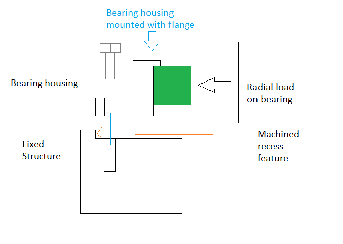
How is shear load transferred from a bearing housing to a structure when using a bolted flange connection that has a tight fit? Is the shear load transferred assuming a non-slip connection generated by the bolt clamping force, or does the shear load transfer from mating surfaces which have a tight fit between the bearing housing and structure.

In my application, I am adding using a radial bearing to allow a table top to rotate. The bearing housing is attached to the fixed structure with a circular bolted flange. The flange of the supporting structure has a recess with a clearance fit H8g7. The operating speeds are low at 7rpm and I don't have any axial loading.
flange_djyfrk.png


Thanks in advance.
 
Replies continue below

Recommended for you

Hi cammecheng

The shear force will be resisted by the friction created at the bolted interface between top and bottom flange, assuming that the bolts are concentric in there bolt holes and not touching the edge of the clearance hole in the bearing housing flange. If the bearing housing flange isn’t clamped with sufficient Bolt force then it will move back and forth until it contacts the fixed structure, if this continues the bearing housing will eventually come loose.
So you just need sufficient clamping force On the bolts to generate Sufficient friction force to prevent the radial force from moving bearing housing.

“Do not worry about your problems with mathematics, I assure you mine are far greater.” Albert Einstein
 
Thanks desertfox

I see the AISC calculation for slip critical connections and the different classes for surface preparation when determining which slip coefficient to use. But of course this is for structural connections. Is there a common friction coefficient to use for mechanical connections which have machined surfaces? There are references to values as low as 0.1 for static steel faying surfaces that are lubricated. Just looking at the typical flanges between motors and gearboxes, this would be a very common type of connection.
 
I'd guess friction would react the load. You'd have to look at the relative stiffnesses of the friction surface and the load path if the flange was pushed against the shoulder. Friction load path seems much stiffer. COF of .1 is a minimum you can generally count on for steel on steel. I think most of the time it is higher than that.
 
Hi canmecheng

I would probably use the 0.1 coefficient and then make sure the clamping force of my bolts exceed the bearing radial load x mu by a factor of at least 2.


“Do not worry about your problems with mathematics, I assure you mine are far greater.” Albert Einstein
 
Canmecheng:
I don’t agree with much that’s been said/thought above, and I wouldn’t be counting on friction to hold that bearing housing in place in an oily environment (in any environment). The shoulder on the fixed structure is machined as a bearing surface for the bearing housing, although your sketch leaves a lot to the imagination about what is really going on with that detail. Is that a plan or elevation view? What’s the shape of the bearing? Show more detail of what is really going on with that system. The bolting of the joint is primarily to hold the two parts tight together, and there is enough play in the bolt holes to allow the bearing shoulder to come into play before tightening the bolts. Although the bolting will offer some frictional component against the radial loading, I would not count on that as the primary load path or reaction feature. I don’t think you normally think of bolting a bearing housing or a flange in the same way as we think of slip critical structural joints. They are certainly not fabed or installed that way.
 
Hi dhengr

What canmecheng is doing with the bearing housing and fixed structure is common in the mechanical engineering world, the radial force on the bearing will possibly be changing direction as the shaft running through it rotates, so relative movement between the fixed structure and bearing housing is likely unless the bolt preload is sufficiently high enough to prevent the radial load from the bearing moving the housing one way or another. Now if he made the bearing housing flange an interference fit within the fixed structure then the bolts merely clamp the two components together and the shear is taken out by the surrounding structure but that wouldn’t be very practical because maintenance on those parts would require them to be disassembled, also assembling the parts would also be quite costly and unnecessary for the application. So either the bolt shanks that might come into contact with the clearance holes ( but you can never guarantee how many of the bolts are in contact or not, in fact you never know because you can’t see them) may take some of the shear load Leaving only the friction force generated by the bolts to take the remainder of the shear. The safest way for the design of that joint is to ensure the bolt preload generates a resistive friction force to prevent the bearing radial force from moving the housing after assembly. One other possible method would be to use shoulder bolts but again these can be quite expensive but because they are fitted bolts they would take the shear, it all depends on application, my company design steel rolling mills and we do this type of thing all the time.

“Do not worry about your problems with mathematics, I assure you mine are far greater.” Albert Einstein
 
Status
Not open for further replies.
Back
Top