Continue to Site

Eng-Tips is the largest engineering community on the Internet

Intelligent Work Forums for Engineering Professionals

  • Congratulations KootK on being selected by the Eng-Tips community for having the most helpful posts in the forums last week. Way to Go!

Shear Lug Breakout Failure When Force is Parallel to the Edge 1

Status
Not open for further replies.

MAB70

Structural
Aug 19, 2019
25
Hi all,

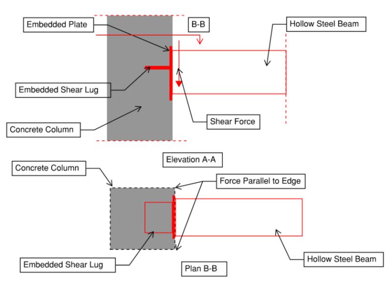
I am connecting a steel beam to a concrete column and having a shear lug to take the huge shear forces from gravity loadings.

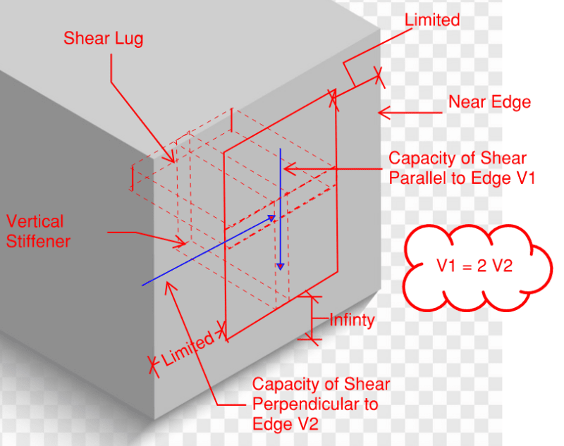
I am designing the shear lug as per ACI 349, the code does not discuss the checks of the shear lug incase the force is parallel to the edge (not perpendicular). However, going through ACI 318-11 appendix D, it says for anchor bolts '' The case of shear force parallel to an edge is shown in Fig. RD.6.2.1(c). The maximum shear force that can be applied parallel to the edge, V||, as governed by concrete breakout, is twice the maximum shear force that can be applied perpendicular to the edge, V⊥''.

My question is does this apply also to the shear lug case? Also, can i use the same special reinforcement specified in ACI 318 appendix D to resist the breakout around the lugs? How and what is the breakout perimeter?
Capture_o2r6ru.png


Thanks in Advance
 
Replies continue below

Recommended for you

Even if you address the prying action, as KootK suggests or otherwise, you still have the issues of how to adequately reinforce the local shear failure zone and how to get adequate concrete consolidation under the shear lug plate. The column base plate example is different in a couple of significant ways 1) The shear lug is vertical, so consolidation of the concrete around the lug isn't an issue. 2) A column would have substantial permanent axial load, providing sustained force from the steel into the concrete, which is not present in the beam connection.

Rod Smith, P.E., The artist formerly known as HotRod10
 
Kootk, I totally agree with you, I do need to add more welded rebars or studs to take out the tension from the eccentricity of the load.
I think we need to differentiate between concrete edge breakout from shear and pryout failure.
The actual breakout plane in your image would be a result of shear pryout which i can understand your concern.However, i have never came across pryout failure mechanism in shear lugs, i only can see it in anchors and studs.
My main question was related to the normal shear edge breakout plane in my case where the force is parallel to the edge and not perpendicular.

My thoughts was to apply same concept of the anchors by considering the following:

1. If the column was with infinite dimensions, I wouldnt check any except for bearing.
2. The column in my case is with limited dimensions, hence concrete edge break out shall be checked.
3. The force is parallel to the near edge and not perpendicular to it, so i would use the same as ACI 318 App D (The maximum shear force that can be applied parallel to the edge, V||, as governed by concrete breakout, is twice the maximum shear force that can be applied perpendicular to the edge, V⊥'')
4. Do my checks on the shear lug by calculating the shear capacity in the perpendicular direction and then multiply by 2 to get the capacity of shear applied parallel to the edge.
5. I wouldnt check pryout failure since AISIC and ACI349 does not mention to do so.

Capture-3_zsxdkl.png


I just need to back it up with any reference.
My principle engineer thinks that the reinforcement of the column will take care of these failures and i dont need to worry about. I am not convinced so i need to do some checks to let it go.
 
Thank you all for your valuable comments, the corbel option is not feasible due to architectural reasons.

@WAROSE, what makes you think that this research is more reliable than the AISIC guidelines, they also have thier own testing as well and also considers the edges same as the research you linked.

 
Mahmoud Belal said:
The actual breakout plane in your image would be a result of shear pryout which i can understand your concern.However, i have never came across pryout failure mechanism in shear lugs, i only can see it in anchors and studs.

The shear lug could have negligible pryout or tension resistance, since it relies completely on bond and friction for that. If pryout is a concern, you need something that has a anchorage in the concrete. If not, then pryout for studs isn't a concern either.

I'm not trying to be belligerent, but I'll put in one more plug for the approach with studs. If you're primarily concerned with shear capacity, providing studs with a total equivalent area to the cross section of shear lug should provide approximately the same shear capacity, without interrupting the vertical reinforcing, and without the concerns about voids in the concrete at a critical location that will not be visible for inspection. Also, the vertical stiffener in your most recent diagram would interrupt or eliminate the horizontal ties through the same critical location below the shear lug.

Rod Smith, P.E., The artist formerly known as HotRod10
 
retired13 said:
KootK's sketch bring out another monster - shear friction.

The reaction developed under the stem tends to chip the concrete away in a manner similar to beam seat with concentrate load on notched concrete wall. Shear friction capacity of the concrete is to be evaluated, and more often than not, special reinforcement is required to resist the force that causing shear, and to prevent the failure of concrete in un-predicable and brittle manners. Note that the critical shear plane is usually steeper than 45°, measured from column face.

There is a methodology laid out in ACI-349 to evaluate shear friction capacity of an embed plate assembly with shear lugs, but tension anchors must be present in addition to the shear lug. Further guidance can be found in the code commentary.
 
@WAROSE, what makes you think that this research is more reliable than the AISIC guidelines, they also have thier own testing as well and also considers the edges same as the research you linked.

I don't know what "ASIC guidelines" you are referring to.....but if it's Design Guide 1, the paper I referenced provides testing results that show the 45 degree method given in DG 1 is light in certain circumstances. AISC agrees because the first time I heard about this, it was in a seminar given by AISC, where they themselves pointed this out and warned us about the 45 degree method.

 
Status
Not open for further replies.

Part and Inventory Search

Sponsor