Continue to Site

Eng-Tips is the largest engineering community on the Internet

Intelligent Work Forums for Engineering Professionals

  • Congratulations cowski on being selected by the Eng-Tips community for having the most helpful posts in the forums last week. Way to Go!

Shear reinforcement of RC beam 1

Status
Not open for further replies.

mats12

Geotechnical
Dec 17, 2016
181
Hi, I have a question about shear reinforcement of RC beam.
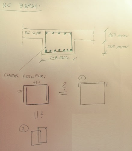
I found a project where shear reinforcement of beam consists of 2 U shaped bars. I wonder is this even OK since this bars should be in tension but they are short - I know they overlap but still? Is this kind of detail more like traditional shear reinforcement with 2 legs (2 bars in tension) - marked as (1) in attached image or more like (2) - 4 bars in tension (4 legs)?

beam_orjy0d.jpg
 
Replies continue below

Recommended for you

It’s not a good detail because the bars aren’t nearly as well anchored.

Codes generally advise against it or simply prohibit it.
 
This is an old detail for members mainly support static gravity load only. Tomfh is correct, don't do it.
 
This is from an old ACI Detailing manual:
aci_js6y4w.jpg
 
From what I'm reading there, they appear to only indicate those are not recommended for cases where they are expected to resist torsion. As retired indicated, this is old detailing for gravity only. I wouldn't detail them this way now, however I feel that they would still be effective at doing gravity only resistance.
 
jayrod12,

You have won the heart of steel workers :) But don't miss the word "static", as loads with dynamic nature tend to have twisting effect, and produce excessive shape deformation. Be aware in using.
 
Per ACI 318-11 - Section 11.4.4, stirrups need to be extended a distance "d" from the compression fiber and "shall be developed at both ends according to 12.13."

Section 12.13 has additional requirements that require hooks at the ends.

 
The weakness of this old detailing can be seen everywhere on outdoor columns/beams with spalled concrete, often times the vertical legs are popped out due to loosing side cover, thus reduce the confining effect on the cores.
 
JAE said:
This is from an old ACI Detailing manual:

The detail in the upper right corner is the one we commonly use in bridge detailing. We typically have very little torsion on components where we have shear ties, though.

Rod Smith, P.E., The artist formerly known as HotRod10
 
Rod,

It was in old ACI detail book but changed later to require 180° hooks. The concrete cover alone was inadequate to confine the 90° bends that supposedly to tie the longitudinal corner bar (in compression)in position, and tended to fail when concrete edges spall. ACI decision was made after rigorous testing and studies.
 
Status
Not open for further replies.

Part and Inventory Search

Sponsor