Continue to Site

Eng-Tips is the largest engineering community on the Internet

Intelligent Work Forums for Engineering Professionals

  • Congratulations KootK on being selected by the Eng-Tips community for having the most helpful posts in the forums last week. Way to Go!

Shear strength of RC section fully in tension

Status
Not open for further replies.

chritsar

Structural
May 9, 2022
11
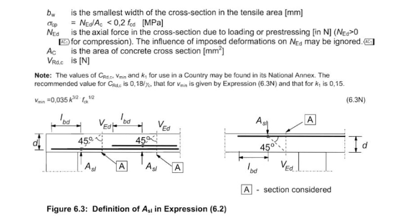
The equation for shear strength of a RC section without shear reinforcement in the various codes takes into account the ratio of longitudinal reinforcement "in tension", which acts as a crack width limiting factor or through dowel action to aid in shear strength.
Example from EN1992-1-1:
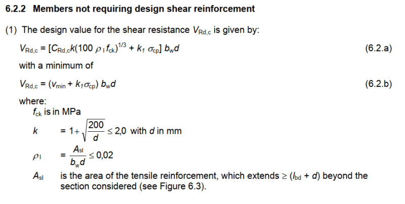
Vrdc_vpitkp.png


The shear strength is analyzed by means of the truss analogy, which in the general case of flexure works with the uncracked section of concrete above the neutral axis in compression. One question is, what happens when the section is fully in tension and the neutral axis is outside of the section? The code formulas seem to be able to be calculated even with tension as axial force, although this doesn't seem very convincing (in the case of EN1992-1-1, it is possible to break the equation with too much tension and get to absurdly low strength, which would yield orders of magnitude different results with another code).

And my main question, which reinforcement should be plugged in the equation as the reinforcement "in tension"? Take the general case of a beam in tension with As,top << As,bot. It is evident that the strain in the reinforcements will also satisfy εs,top >> εs,bot, implying that cracking will be substantially worse in the top side. Would that be a clue that the top reinforcement should be plugged in the equation, no matter the sign of flexure?
 
Replies continue below

Recommended for you

Normally I would take Concrete shear capacity as 0 if the section is fully in tension.

If you wanted to base it on the formulae,

If you considered both top and bottom steel to be in tension, then d would be much smaller as it is the centroid of the tension steel.

So
Ast / bd for bottom steel only in tension

would be basically the same as

(Ast + Asc) / d with both equal and in tension and d the centroid of all of the steel!

plus sigmacp in the formula is negative as in the Ned / Ac term.

Considering after all of these calculations, if shear reinforcement is required, Eurocode then sets VRD.c t = 0 for the calculation of the shear reinforcement requirements, I would assume 0 anyway and put in shear reinforcement for the full shear.
 
Having worked with Eurocodes in past , my points are;


- The clause 6.2.2 for Members not requiring design shear reinforcement and the remaining part of the subject Expression is,

EXPRESSION_6.2_scxezw.jpg


- AFAIK , the equation 6.2 has essentially been derived for beams, failing in shear flexure. When the RC member experience full tension , in this case the axial stress ( σcp ) will be negative . One can easily see the expression 6.2 will be zero if the term in parenthesis is zero.

- If the design shear force is larger than ( VRd,c ) shear reinforcement is necessary for the full design shear force and the shear reinforcement will calculated with the variable inclination truss analogy.

- still trying to imagine an RC member experiencing full tension, moment and shear ..Will you pls provide more info what kind of member is this ?

- I would prefer the use of structural steel or composite member for such case.

My opinion ..


Tim was so learned that he could name a
horse in nine languages: so ignorant that he bought a cow to ride on.
(BENJAMIN FRANKLIN )
 
rapt said:
So Ast / bd for bottom steel only in tension
would be basically the same as
(Ast + Asc) / d with both equal and in tension and d the centroid of all of the steel!

The disturbing fact about this is that the second equation would give a drastically larger tensile reinforcement ratio to plug into the equation, albeit the reduced effective depth will reduce the overall result of Vrd,c.

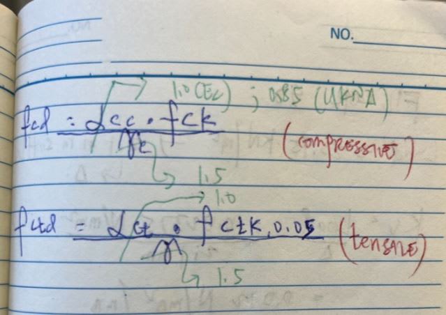
The code actually intends to have shear strength for members in tension as explained in the designer's guide:
vrdc_iafmce.png


HTURKAK said:
- AFAIK , the equation 6.2 has essentially been derived for beams, failing in shear flexure. When the RC member experience full tension , in this case the axial stress ( σcp ) will be negative . One can easily see the expression 6.2 will be zero if the term in parenthesis is zero.
It was derived for beams but also used for slabs and columns which can lead to inconsistencies in some cases. In the case of tension, the expression will not necessarily be zero, depending on the value of σcp it might only reduce the result.

My question mainly was, which reinforcement should be plugged in the equation? Seemingly from the theory of shear with the truss analogy it shouldn't even work for members fully in tension, but the code is inconsistent and intends for such members to have a calculatable shear strength. A bridge deck composite slab for example would always have to be provided with shear reinforcement if shear strength should be 0 when the section is in tension.
 
chritsar said:
A bridge deck composite slab for example would always have to be provided with shear reinforcement if shear strength should be 0 when the section is in tension.
There is not a pulling axial tensile force (just tension from bending) in a bridge deck reinforced concrete slab, so the section has concrete in compression and a strut-and-tie analogy applies. In the bridge longitudinal direction, the shear capacity is most often attributed to the steel girders only, so no worries there either.

If external loads cause large axial tension (not common in buildings or bridges), the best bet is prestressing or switching to steel or composite steel-concrete.
 
Oops. bad mental math! You are correct basti214.

I would still ignore the Vrd.c calculation and take the full shear on the shear reinforcement.
 
Status
Not open for further replies.

Part and Inventory Search

Sponsor