Eng-Tips is the largest engineering community on the Internet

Intelligent Work Forums for Engineering Professionals

  • Congratulations waross on being selected by the Tek-Tips community for having the most helpful posts in the forums last week. Way to Go!

Shear transfer through diaphragms 2

Status
Not open for further replies.

andr3w44

Civil/Environmental
Aug 17, 2017
9
0
0
US
Hi all,
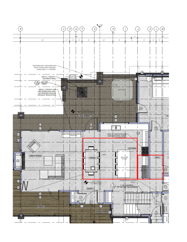
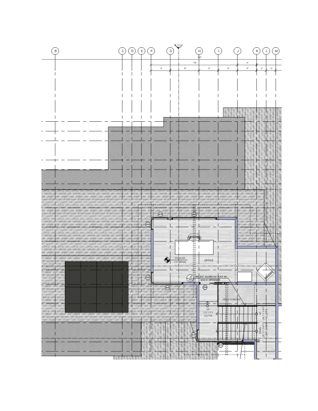
I wanted to hear some thoughts and opinions on shear transfer of a 2-story home. The upper roof is going to be resisted by a shear wall along gridline F on the "upper floor plan."(picture attached) Could you then transfer this load to grids B and K/M on the "lower floor plan?" Or Even drag it to the wall along line J? The red squares in the "lower floor plan" represent the upper floor diaphragm, the rest would be roof diaphragms. With the snow loads, seismic controls over wind in the area.
There is one engineer saying that I cannot resist shear along line F at the lower lever, I think through the roof and floor diaphragms you could(even if blocking is needed depending on the loads.)
LOWER_FLOOR_PLAN_zedh2v.png
UPPER_FLOOR_PLAN_gt2vzv.png
 
Replies continue below

Recommended for you

Yes, and for cases like this (where there is discontinuous load path, you want to use the Omega type seismic loads to detail the transfer of shear from the upper shear wall into the diaphragm.
 
As far as I'm aware, that book is the wood diaphragm bible. I can't speak to whether it has specific examples similar to your case, but if any book has guidance, it's that one.

Really you just need to look at the load transfer mechanisms at each location, top of second floor walls to roof diaphragm, bottom of second floor walls to second floor diaphragm, T/C forces at ends of second floor shear walls to second floor framing. And then second floor diaphragm loads to main floor shear walls etc. Follow the load until it's into the ground and you should be good to go.
 
I'll come in with a dissenting opinion.

1) Can you do this? Sure, I know of know prohibition so long as you're engineering the load path.

2) Should you do this? I don't feel that you should. My reasoning for that:

a) I think that the IRC let's you transfer 4' laterally or something like that? You are not beholden to that if you're engineering the load path but, at the same time, I feel that most of the IRC limits amount to simply good engineering practice. I try not to stray too far from the IRC requirements personally. And you are proposing straying very far from the IRC requirements in my opinion.

b) The stiffness of your upper level wall on grid F will now be heavily dependent upon the lateral stiffness of the diaphragm that supports it. When you account for this, as you should, you may find that the shear wall on grid F ceases to draw a meaningful amount of lateral load. The upper floor area may, effectively, turn into a three sided building. This will be exacerbated by shear wall rotation if the chords of the shear wall on grid F terminate on top of a transfer beam rather running directly to ground.

c) In my experience:

i) Transferring shear between a floor and roof at the same level is easy but:

ii) Transferring chord forces between a floor and roof at the same level can be very difficult. Things just never line up quite right.

3) You're in California and we all know that the assumption of a true flexible diaphragm is mostly bullshit. That means that you're introducing a pretty nasty torsional irregularity into your structure.
 
This is very common feature of residential lateral systems in California. Almost every 2-story house is going to have at least one of these. The supporting beam is designed using omega, the diaphragm is designed using 125%of the demand.
 
Yeah, I've done a number of similar residential buildings like this in California. For the same architect I suspect. For a jurisdiction with some of the world's best structural engineers in general, I find that much of what is commonly done residentially in California is still full of questionable design choices. As with most places, the fees are still rather small and the pressure to make any crazy thing work rather high. CA member sandman21 warned me about this years ago, when I first got into the work, and he was not wrong.

Sure, Omega and 125% buy you a little wiggle room. That stuff is meant to cover demand uncertainty, however, and not design slop / inaccuracy. If anybody can show me a shear wall calc that properly addresses all of the stuff that I mentioned in my previous post, I'll happily eat my shorts.
 
Is anyone familiar with this book "The Analysis of Irregular Shaped Structures Diaphragms and Shear Walls"

I wouldn't call it the "bible" of wood diaphragms, but it is an excellent reference. It forces you to think logically about load paths for irregular shaped diaphragms. How it affects shear and detailing around corners and such. Kind of like doing force transfer around openings for shears walls.
 
Status
Not open for further replies.
Back
Top