YC611
Structural
- Oct 12, 2023
- 24
Hi all,
Long time lurker here and happy to finally decided to join the forum.
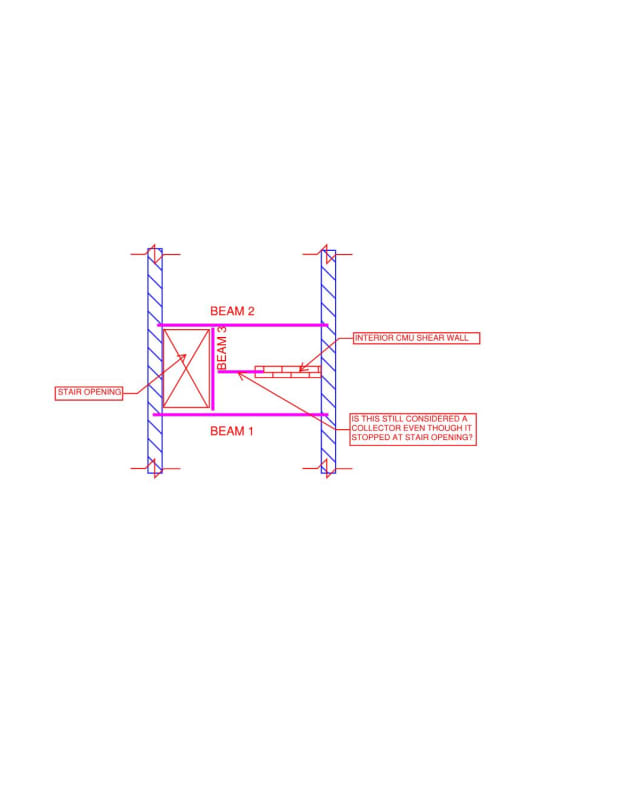
I am currently involved in a townhouse alteration in NYC and I have to design the lateral force resisting systems based on the architectural plans. This building is approximately 20'W x 50'L x 40'H (typical residential building). As always, the front and rear facades are more than 50% of window and door openings. So my best options are to utilize the interior shear walls. However, for one of the shear walls, I have a stair opening on the way of the collector. I was wondering if I can still analyze and design it as collector. Please see sketch attached.
My guess is that: lateral force >> diaphragms >> beams 1 and 2 >> beam 3 >> collector >>shear wall.
If it isn't the case, how will the lateral load be transferred to the shear wall in the current setting? Or that it is not working and I will have to find a new shear walls elsewhere.

