Continue to Site

Eng-Tips is the largest engineering community on the Internet

Intelligent Work Forums for Engineering Professionals

  • Congratulations KootK on being selected by the Eng-Tips community for having the most helpful posts in the forums last week. Way to Go!

Shear Wall Design - Model With or Without Piles as springs? 1

Status
Not open for further replies.

T2ioTD

Civil/Environmental
Feb 4, 2020
38
By believing I should seek precision in my model (20 story building with small floor area), I opened a pandora box and I don't know how to proceed.
I know the majority model their superstructure with supports as pinned/fixed even if there are piles beneath, but I figured out that maybe by modeling the piles I can simplify further tasks like pile design and mat foundation. The problem is that I have now very large deflections and very large moments on the shear walls. I don't know what to do with these forces. Should I revert to the model with pinned supports to design the shear walls?
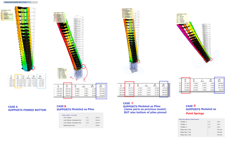
The picture shows 4 approaches of modeling. In all cases, I showed the value of the deflection of same point (approximately the same point) at the top left corner of the bldg, and the value of the forces at the lower shear wall at right. The same load combination is used in all the models:
1.35 Dead + 1.05 Live - 1.5 Wind.

Model 1: Pinned supports
Model 2: Piles as linear spring (in x,y and z directions)
Model 3: Same as Model 2, but piles, in addition to the linear springs, are pinned in the bottom
Model 4: Piles as point springs.

I would much appreciate your help.

Please consider opening the link below to view a high resolution image. I don't know why Eng-Tips has very low resolution for the uploaded image (or do I miss something when using the upload feature?)
tmp_xfkvkc.png


The link to the hi rest image:
 
Replies continue below

Recommended for you


Will you please post some more information? 20 story building should normally have a basement floor and raft foundation.
If this assumption is valid, the horizontal force would be resisted by basement floor walls and raft foundation.

I would model the walls FEM plane stress element supported on pins on the raft and the model the raft foundation with plate bending elements supported on piles modelled as springs.

My opinion..


Use it up, wear it out;
Make it do, or do without.

NEW ENGLAND MAXIM


OP Here.

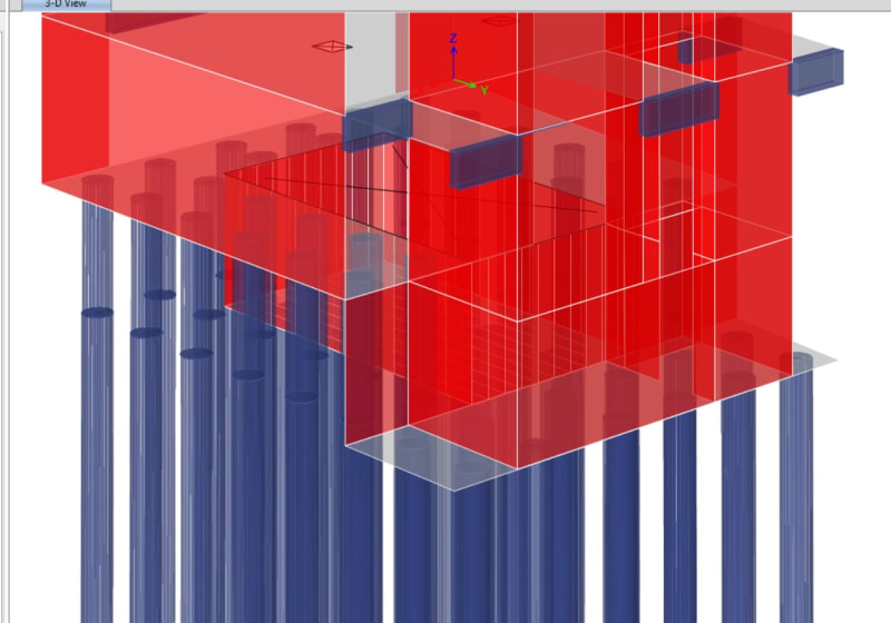
There is no basement per se, but the staircase and lift continue one level below ground, where a septic tank should also occupy the center as the picture follows:

tmp_q2e1mc.jpg
 
Through the different methods - are the piles working or have they exceeded their allowable capacity?

How thick of a pile cap do you have in your ETABS model? Have you used SAFE to design a pile cap for Method 1?
 
I don't have any experience with 20 storey buildings so I can only limited advice
However, our code requires us to consider soil-structure interaction in our designs - that is effectively what your pile design is
If deflections are OK when using a simplified model (no piles) but not OK when using a more accurate model (including piles) then that indicates that you need to be considering some sort of model with piles
Common sense agrees with this - the building will be sitting on piles and the supporting soils are not infinitely rigid so the building is effectively higher/more flexible than the 20 stories above ground alone would indicate - we therefore expect more deflection in the structure

So, in my books, you definitely should be accounting for these effects
As to how to do that - that's a tricky one!
I would think that modelling the piles in with lateral soils springs provided by your geotech would be the way to go
Here, seismic design governs pretty much everything, so this would likely give you benefit by reducing the building's period and dropping the loads
I doubt that will be the case here but there's not much to be done about that - your model has to be the simplest realistic model after all
 
problem is that I have now very large deflections and very large moments on the shear walls. I don't know what to do with these forces.

Is your spring stiffness correct? It doesnt look too stiff without looking into detail (have you modeled ultimate limit or working load limit on pile stiffness - are your loads ultimate or working load?). Try near infinite stiffness on your piles and see what results you get.

Also consider this:
1. lateral resistance of mat/pad foundation due to base friction.
2. Lateral resistance of mat/pad foundation due to passive pressure.

but I figured out that maybe by modeling the piles I can simplify further tasks like pile design and mat foundation

For a small footprint building like yours, its a lot simpler to do this by hand. Basically you get a cantilever beam, there is a moment and shear component at the base, forces will be distributed by stiffness.
 
OP Here.

Mat thickness is 130 cm. I wish I can upload the model, but I don't know how. The piles reactions are all below 2000 KN, and I think I can achieve that given than the soil report indicated SPT refusal below around 11 m.

I think too that the stiffness of the piles are not realistic, but here is what I have done to achieve them:

Vertical Springs:
- Calculated Meyerhoff pile bearing capacity. 2,661 KN
- Calculated s1, s2, s3: the 3 settlements. Total Settlement mm 141.3
- Divided 2661/141.3 = 19,000 KN/m
- Decided I can go even higher, so I decided for a value of 50,000 KN/m
- I divided the 50,000 by pile length, 14m (but I think I will end up with 16m piles) and I got 3500 KN/m/m
- I entered 3000 KN/m/m in Ebs

Horizontal Springs
- KSB Soil 40,000 KN/m³ KN/m/m²
- Pile Diameter 0.6 m
- 40,000 x 0.6 = 24,000 KN/m/m
- I entered only 20,000 in Etabs


If SPT refusal below around 11 m and if the pile depth 16m , literally 5 m will be installed at refusal layer and the calculated 2,661 KN pile bearing capacity should be safe bearing capacity. 600 mm dia implies bored pile and my experience is
the settlement of the pile head at the proof test load is unlikely to exceed 50 mm. and for 2000 kN design load , should be around 20 mm .

In this case Kv= 2000/(0.02)= 100000 kN/m .

Regarding Horizontal Springs , i agree with your calculation but for cylindrical shape , half of the calculated value should be used. However , i should consider the passive thrust for raft found . 130 cm thick and foundation walls .

My opinion..


Use it up, wear it out;
Make it do, or do without.

NEW ENGLAND MAXIM


Status
Not open for further replies.

Part and Inventory Search

Sponsor