Continue to Site

Eng-Tips is the largest engineering community on the Internet

Intelligent Work Forums for Engineering Professionals

  • Congratulations KootK on being selected by the Eng-Tips community for having the most helpful posts in the forums last week. Way to Go!

Shear Wall Transfer Beam 3

Status
Not open for further replies.

SteynvW

Civil/Environmental
Feb 1, 2016
108
I currently have a shear wall that has to transfer the load to the columns.
I have looked at systems that use a beam (in the same plane as the wall) to
transfer the loads from the wall to the column. The problem that I do a
finite element analysis it shows that the bottom part of my wall or beam if
I had one will be in tension. What advantage will I gain from using a beam
and not just put my wall down on the columns with column heads?
 
Replies continue below

Recommended for you

OP said:
Thank you very much for you time.

No sweat. Helping each other is our thing here.

OP said:
South Africa.

Thanks. I asked because the code that you're using will impact your assumptions regarding transfer of lateral shear from the wall into the slab. As rapt mentioned, the detail would be vertical u-bars extending into the slab and wrapping around some longitudinal steel. Personally, I feel that's sufficient to develop the u-bars on either side of the horizontal cold joint. However, in the US and Canada, there is no provision explicitly allowing you to consider a u-bar like this to be developed any better that a straight bar with a standard hook would be. And regular hook bar development in a 200 slab will be a challenge for most u-bar diameters. For this reason alone, you might want some manner of thickening below the wall if not a full blown beam.

rapt said:
And how is the whole connection going to work with the tension tie above the top of the slab?

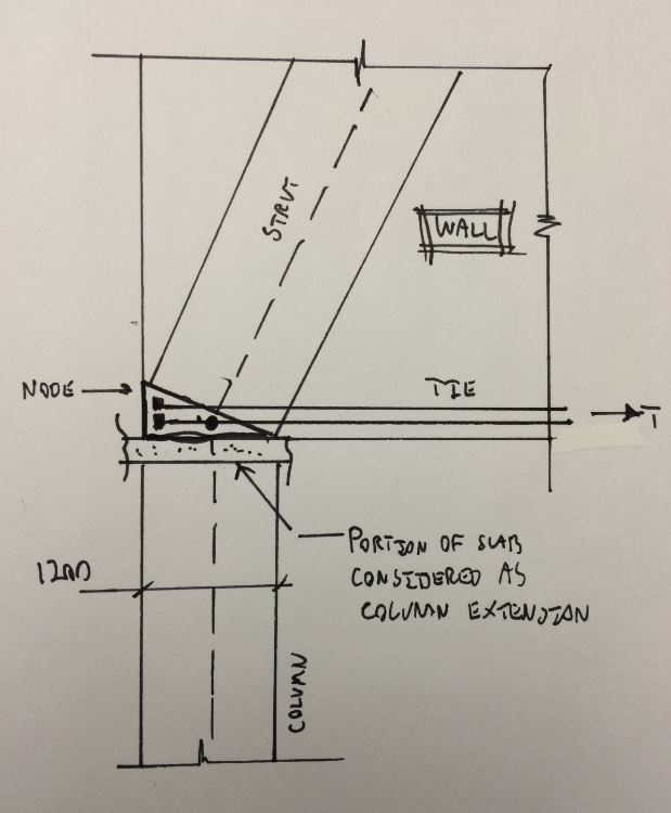
As shown below for the gravity case. If you envision the bit of slab sandwiched above the column as simply an extension of the column, the detail become that of any simple span, column supported deep beam.

rapt said:
There is no way I would detail it as you have shown. Why, because it feels better to me. But that is just my opinion.

Sure. And the preference that I've expressed here is simply my opinion. I believe that both details can be made to work and, in truth, my preference for placing the tie in the wall is slight. Certainly, placing the tie in slab facilitates a very appealing tie anchorage scenario.

No matter which approach is selected, the diagonal compression force needs to be "turned" vertical before it passes into the column. As a matter of general philosophy, I find it preferable to affect that change prior to the strut crossing the cold joint. One less thing to worry about in my estimation. I, like many other engineers, have reservations regarding shear friction. And, as the application gets more critical and veers further from the simple mechanisms tested, the more reservations I have.

Capture_mc4v7h.jpg


I like to debate structural engineering theory -- a lot. If I challenge you on something, know that I'm doing so because I respect your opinion enough to either change it or adopt it.
 
Looking at the whole set up now that we have a drawing, I would design the end 1200 off the wall at each end as a column to carry the load full height. Load will transfer across to it rather than down to the bottom and then across. Increase the width of the wall at the ends at least to make it work as a pair of columns.

If the wall is taking sway loadings of any sort (wind or earthquake) then the loads are going to be at the ends any and the ends have to be designed to take those loads anyway. Those loads may be higher than the averaged gravity loads

Only the bottom few floors worth of load will transfer across in strut tie action.

PS hate the detail with the tie above the slab. If you have to have a tension tie extend it below and make it the width of the column at least. Maybe even make the first floor height of the wall the width of the column, 300 as well. The column bars will have to extend through the slab anyway and they will provide the horizontal shear required.
 

I caluclated the forces and required reinforcing according to our code using your proposed strut and tie layout.
(Please see attached). The first one is with a 2/1 ratio and the second one is
with a 3/1 ratio. The increase in angle has significant influence on the tension
reaction in the strut and tie model.

1. Is it fair to use a 3/1 ratio or even a 4/1 ratio considering my wall is 16 stories high and will in actual fact increase ration if the wall height increases?

2. The transfer from compression to tension has to be done through shear at the node, is the shear just in the marked area at the bottom of the pdf or is it continuous through
out the bottom of the wall?
 
 http://files.engineering.com/getfile.aspx?folder=a2c53faf-294a-434b-a695-79640df6d08a&file=SKMBT_C28016020409540.pdf
1) I don't recommend it as I don't believe that the local, disturbed region mechanics would change in response to additional wall height beyond a certain minimum. You should be able to test this with your FEM model if you care to. Adding or deletting a couple of stories should alter the magnitude of tensile stresses at the bottom of the wall but not the height of the wall over which those stresses occur.

The 2:1 is based on research and shows up a few places in various standards which gives it some credibililty in my opinion. And this is a situation where I wouldn't skimp on reinforcing. 7000 mm^2 seems reasonable to me. Assuming a single mat in the wall, I might install 12-30M at 100 in a band at the bottom of the wall. It's a fairly narrow wall for the application and getting good concrete compaction aroumd the bars will be critical.

2) Refering to my sketch, all you need to do for shear transfer is develop the tie bars to the left of where they first pass into the strut. You'll have nearly four feet to develop the bars here which should be plenty.


I like to debate structural engineering theory -- a lot. If I challenge you on something, know that I'm doing so because I respect your opinion enough to either change it or adopt it.
 
I put together a quick calc to test shear friction across the cold joint were you to put your tie in the slab rather than the bottom of the wall. According to my estimate, the joint would be considerably over stressed. And my calculation was based on the maximum permissible shear stress, regardless of the amount of reinforcing crossing the joint. In this instance, I feel that this supports my preference for installing the tie rebar above the slab/wall cold joint.

Capture_kmwkir.jpg


I like to debate structural engineering theory -- a lot. If I challenge you on something, know that I'm doing so because I respect your opinion enough to either change it or adopt it.
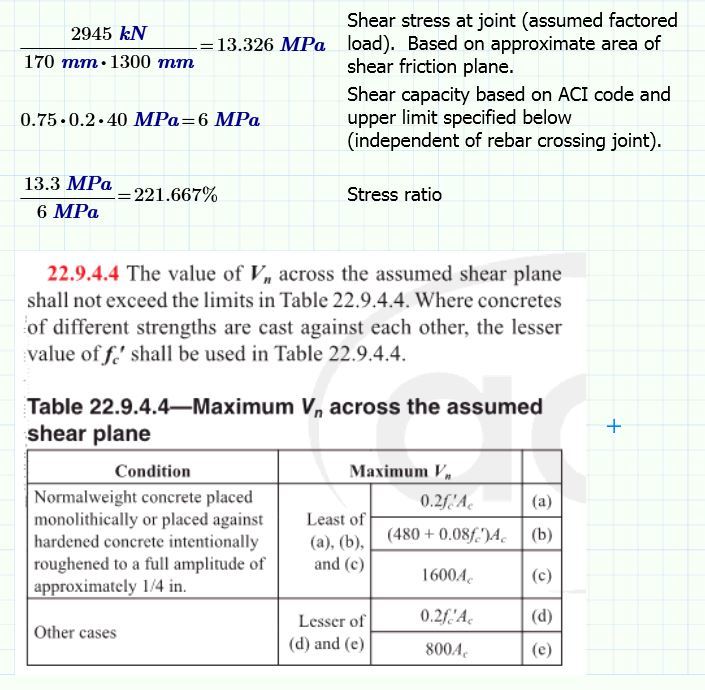
 
22.9 applies to all concrete though, even monolithic - so aren't you going to get the same overstress/result even when placed above the slab?

Ignoring the above - I don't see any problem with placing it above the slab in the base of the wall and tend to agree on it's merits. I also agree that this is no place to skimp on steel. Even if you placed the required steel in the base of wall and then placed that same amount distributed in the slab (i.e. 2x the required) you're not talking about a lot of steel.

Stey - You have not asked about other issues with this so maybe you've already thought through them but: you should check your code for any penalties for this system/irregularity, you'll need to analyze/design your diaphragm to take that shear elsewhere (make sure software isn't using rigid diaph), if you are getting net uplift you'll need to check/develop that tension through this joint and also account for the reduced/cracked stiffness of the column.
 
Bookowski said:
22.9 applies to all concrete though, even monolithic - so aren't you going to get the same overstress/result even when placed above the slab?

Exactly right. It would be better but not good enough. I don't believe it for a second but that's how it's presented in the code.

I like to debate structural engineering theory -- a lot. If I challenge you on something, know that I'm doing so because I respect your opinion enough to either change it or adopt it.
 
Actually, upon further consideration, I suspect that monolithic shear friction not working may be evidence of the the strut itself not being adequately proportioned. I initiated an interesting thread here a while back where I basically ended up proving to myself that no monolithic element should ever fail in shear friction. In fact, the mu factors appear to be calibrated almost right on the money to make that the case.

I like to debate structural engineering theory -- a lot. If I challenge you on something, know that I'm doing so because I respect your opinion enough to either change it or adopt it.
 
Yes, this thread. I agree, shear across any plane must be adequate(not just diagonal) based on statics but that it is almost always satisfied and thus not necessary to check. Although in that thread I had pointed out some articles about direct shear failures, last post in the thread - everything that I found was related to impulse/blast loading.
 
It does create quite a concern. Im am currently looking at adding a "beam" (600mm wide and deep or 23,622 inches) beneath the slab. The main transverse shear will be here and a reduced shear force will be at the cold joint as well as the 170mm wall.

According to my FEA the transverse forces above this beam is about 30% of the maximum at the wall slab connection.

What are your thoughts?
 

Have a look at the enclosed article regarding the design of deep beams. You will want to provide additional horizontal reinforcement distributed through the bottom several feet to prevent the vertical cracks caused by the near vertical compression struts (the refined model in KootK's second post is more appropriate than the 2 to 1 compression struts).

As for your original question, and as it regards to vertical loads only, I do not see any advantage for providing a beam below the wall except to relieve potential reinforcement congestion. A beam below the slab should just be treated as an insignificant additional height to your 15 story deep beam.
 
As I see it, the main benefit of using the beam to solve this particular issue is that it enables you to make the horizontal dimension of your node wider than your column. I'd still investigate shear friction at the cold joint. You'd just have a larger area to work with.

I like the beam idea as it allows you to increase the width of your node and reduce the stress on the diagonal strut. That said, I'd personally still put the tie above the cold joint, even with the beam.

I've got a couple of strut and tie models floating around in my head for the beam scenario. Let us know if that's something that you'd like to explore further.

I like to debate structural engineering theory -- a lot. If I challenge you on something, know that I'm doing so because I respect your opinion enough to either change it or adopt it.
 
The problem with putting the tie above the slab is that it is going to be hard to place +/- 8000 square millimeters into a 170mm wall. It can be installed over a 500mm vertical section. The belt and braces idea of putting the steel into slab and wall is quite an attractive solution that will make me sleep a bit better at night. :)
But there are more or 50 of these walls, so over-designing a repetitive member is not going to be that economical.

But I think just because of the increase of the transition zone between the wall (increase in node size) is almost enough reason to use a beam or rather a column head.


Status
Not open for further replies.

Part and Inventory Search

Sponsor