Continue to Site

Eng-Tips is the largest engineering community on the Internet

Intelligent Work Forums for Engineering Professionals

  • Congratulations waross on being selected by the Eng-Tips community for having the most helpful posts in the forums last week. Way to Go!

Shear walls on a steel beam 1

Status
Not open for further replies.

Sandychan

Structural
Sep 25, 2015
22
Hello everyone,
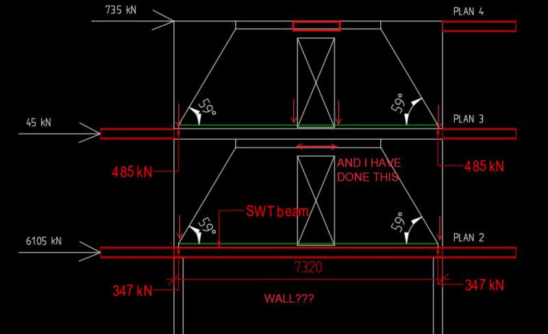
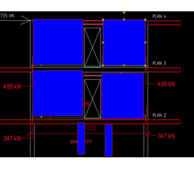
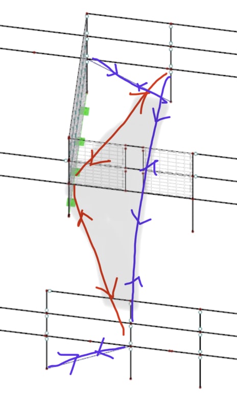
I am working on design of precast shear walls that have a system as shown in the Figure 2. The system was subtracted from the whole model as shown in Figure 1. SWT beams on Plan 2 (steel beams with an opened top for casting in concrete, Figure 4) will not carry vertical loads from the walls. The vertical loads are planned to go the columns heads through strut and tie model and reinforcement that serves as ties will be placed in the wall under the door. Which mean the beam will not be integrated to the wall for vertical load carrying purpose.

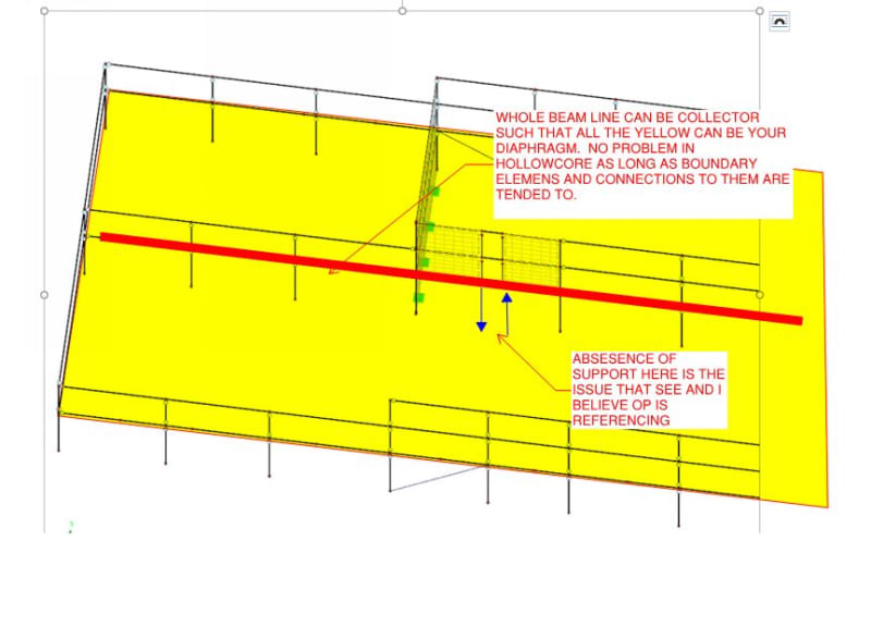
However, accumulated shear force at the base of the lower wall shall be transferred to wind bracers on the outer facads through hollow cored slabs carried by the SWT beam. Which mean the base of the wall need to to be connected to the beam anyway to transfer horizontal force to hollow core slabs.

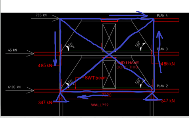
I have lookup and found a simplified loading system for designing coupled shear walls, Figure 3 and it shows overturning moments at the base of the walls (M1 and M2). At this point I feel really confused. How should I take care of M1 and M2 when the wall and the beam are not integrated for vertical load? Especially for M2, it creates tension of right edge of the door, how can I neutralize that tension when my compression force is already directed to the column head through a diagonal strut. Please find attached the file containing figures stated above.
Thank you so much in advance for any suggestion.



 https://files.engineering.com/getfile.aspx?folder=11dc9e12-d37e-4e07-a439-603311d652fa&file=Figure_file.docx
Replies continue below

Recommended for you

I feel that you might be trying to chase down a system that is simply ill advised based on the proportions and what you currently have to work with. Yeah, coupled shear wall systems are a thing but the shear walls typically make it down to ground or some manner of rigid-ish base support.
 
Hi Kootk,
I have to say that I feel the same that the system is not that good.Unfortunately, there are no other shear walls in the long direction on the top 2 floors except these 2. I just have to find the way to make walls work. Beside this ill system, I sadly don't know how to design these walls subjected to lateral forces. How does strut and tie model for horizontal loads look like for this particular case? All I can think of is that those lateral loads give base moment. With a lever arm equal to a wall length, I will get tension on the left column and compression on the right one. For the tension side, as long as I have enough vertical loads on the column heads, uplift should not be an issue. Is this a way to think go?
 
Take the advice above. Can you brace another bays to relieve shear demand on these walls.
 
Some comments...

image_g0lvsc.png


way back, when I first started I did a bunch of medium rises (20 storeys)with shear walls and corridor opening in reinforced concrete. There were several ACI articles by Rico Rossman (sp?) on coupled shear walls... before the advent of personal computers... solutions in non-linear, non-homogeneous differential equations (couldn't do them now; I'm way too old)... I've often treated shear walls as providing reactions only at the corners/edge.

If no wall at lower level then your columns have to be much wider... but can be accommodated using the same point load approach.

Rather than think climate change and the corona virus as science, think of it as the wrath of God. Feel any better?

-Dik
 
Hi Dik,
There is no wall under SWT beam. Accumulated base shear force on Plan 2 shall be transferred to outer facads wind bracers through hollow core slabs. Looking at your sketch, I don't understand why we have compression force on each door edge on Plan 3. Could you explain that that a little more? Thank you.
 
op said:
How does strut and tie model for horizontal loads look like for this particular case? All I can think of is that those lateral loads give base moment. With a lever arm equal to a wall length, I will get tension on the left column and compression on the right one. For the tension side, as long as I have enough vertical loads on the column heads, uplift should not be an issue. Is this a way to think go?

I'm going to abstain on the details until we have some kind of system that isn't missing important load path bits. The least invasive way that I can think to get you back to something plausible is shown below with a couple of columns inserted in the lower floor to resolve overturning in your walls. Your coupling beam idea does, in fact, create a valid load path. I just don't see it being stiff enough to be worthy of serious consideration.

C01_jcaipy.jpg
 
Hi Kootk,
My insecurity is running high right now. Besides what you guys try to warn me, my gut feeling make me question about this structural system as well. I will have a serious conversation with my project manager tomorrow. I realize that we need serious reconsideration about the system. Thanks for raising a red flag. I will get back if we have any update on system improvement.
 
Sounds like a good approach SandyChan. I'm all for aggressive, creative problem solving but some problems just aren't your problem to make right. I get into this sometimes with my own precast work. Goes like this:

EOR: do something crazy!

PRECASTER: no problem, here's your fee. Show it to kootk later.

KOOTK: can we make some changes to make this impossible thing possible?

EOR: only if those changes are zero cost and zero impact!

KOOTK: too bad, so sad, there will be both cost and impact.

EOR: the precaster bid this so you have to pay for any changes.

PRECASTER: no thanks, what you asked for was impossible.

KOOTK: dear precaster, please show me crazy stuff before you bid it...


Not so sure of the reason for the insecurity... some good info, above, on what to avoid.

Occasionally, I've used the compressive forces to reduce/eliminate the point loads on the interior of the span. As far as resisting the shear; this can be accomplished via steel sections (have to watch deflections, though) with the beam connected to the precast shear wall... not too difficult even for large forces with steel. I've done many precast and masonry shear walls, where the precast beam (for masonry, too)over the corridor is only a 8" deep with the space between the HS slabs concrete filled acting compositely with the beam to give an equivalent depth 8" deeper than the precast beam, with single leg stirrups transferring the shear.

Rather than think climate change and the corona virus as science, think of it as the wrath of God. Feel any better?

-Dik
 
When you place a infinite rigid wall on the flexible beam/slab system, you have to think the deformation compatibility between these two elements. A reinforced masonry wall with shear studs seem necessary to bond all elements together, and acts as an integral structure. In this scenario, the lower columns would be the weakest links to be focused on.
 
dik said:
I've done many precast and masonry shear walls, where the precast beam (for masonry, too)over the corridor is only a 8" deep...

Have you done that where the shear wall system doesn't make it to ground/foundation/transfer? That's the kicker here: there's no plausible load path for the overturning in the solid wall bits.
 
It will help if the bay below can be braced.

image_b4ucvs.png
 
Hi r13,
Do you mean instead of shear walls I use diagonal steel bracers to stabilize that bay?
 
As mentioned previously, you can find the ways to make the walls and boundary elements (steel beams, columns, concrete slabs) acting as an integral unit, usually through reinforcing steel and shear studs, and treat the unit as a huge shear wall, or deep beam. In order to accommodate/support the deep beam, the lower columns need to be strengthened, or the bay braced.

You surely can brace the two bays, but I doubt the effectiveness due to the door openings. I still prefer to provide bracings to other locations to meet the lateral load demand, but free up the two bays, so the masonry walls will be there for the gravity load only.
 

Yup... including a 14 storey building in Regina, where the shear walls bear on a large transfer girder (about 6'x9'x130') spanning at right angles to the shear wall to transfer loads to shear walls below at different spacings to accommodate parking below (different sort of shear transfer problem)... The OPs situation is not uncommon because corridor openings above often don't accommodate parking drive isles below...

Rather than think climate change and the corona virus as science, think of it as the wrath of God. Feel any better?

-Dik
 
dik said:
Yup... including a 14 storey building in Regina, where the shear walls bear on a large transfer girder (about 6'x9'x130')

That would be a "nope" then as OP has nothing resembling the transfer girder here.

KootK said:
Have you done that where the shear wall system doesn't make it to ground/foundation/transfer?

dik said:
The OPs situation is not uncommon because corridor openings above often don't accommodate parking drive isles below...

You must be missing something here dik as OP's condition isn't remotely common.

The corridor over parking example is different as any sane engineer will still be transferring the walls out either through:

1) Transfer beam(s) under the wall ends

2) Transfer slab under the wall ends

3) Parkade columns under the wall ends.
 
Is this the intended lateral load path, diaphragm action to transfer the horizontal kick from the base of the shear wall out to the perimeter braces? See crappy phone markup below...

It could work in theory I guess. Not ideal by any means and you’ll no doubt have second order effects to consider as the whole thing is just not stiff enough for me - but could be done I guess. How you justify that diaphragm action from the hollowcore (presumably with reinforced structural topping??) is a different matter. You might consider a horizontal wind girder beneath the floorplate?


25D50F48-7CAB-42AA-803B-1D09987FE846_v4h52z.jpg
 
Hi MIStructE_IRE,

Your sketch shows the intended load path and that is correct that the diaphragm action contributed by reinforce topping over hollow core slab. I am not really the one designing the slab. It was my project manager but what he explained looks like your sketch. It is another engineering contractor who does the foundation. I have to take a look if they have wind girders beneath the foot plates but I assumed that they have that once they see the presence of diagonal wind braces.

 
I expect that there's quite a bit of diphragm available to get the lateral transfer done, even if the though roof is not hollow core.

C01_ohqgnr.jpg
 
Status
Not open for further replies.

Part and Inventory Search

Sponsor