Continue to Site

Eng-Tips is the largest engineering community on the Internet

Intelligent Work Forums for Engineering Professionals

  • Congratulations waross on being selected by the Eng-Tips community for having the most helpful posts in the forums last week. Way to Go!

Shear walls on a steel beam 1

Status
Not open for further replies.

Sandychan

Structural
Sep 25, 2015
22
Hello everyone,
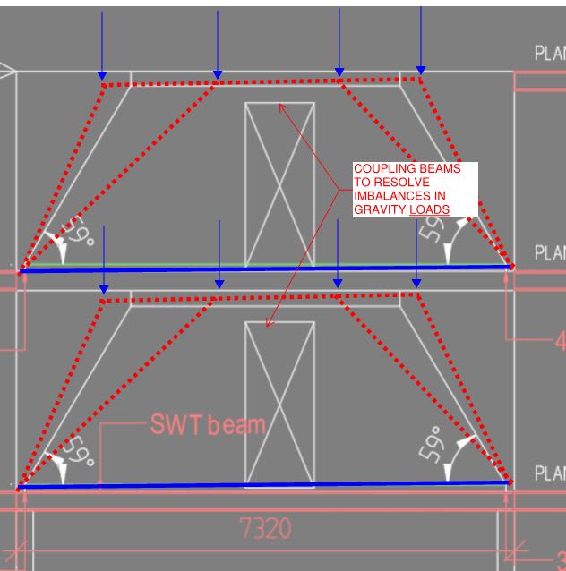
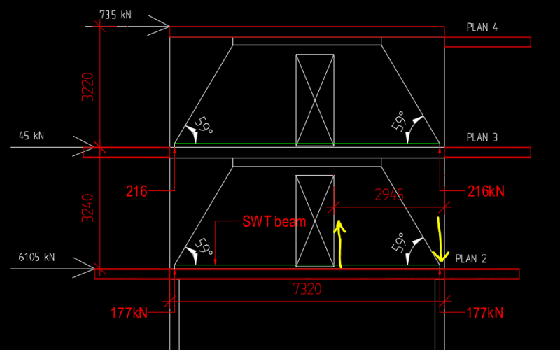
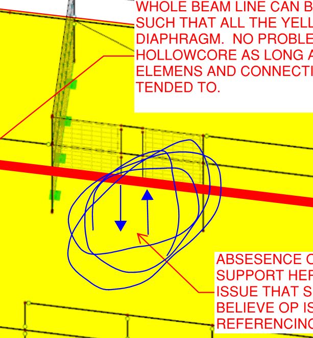
I am working on design of precast shear walls that have a system as shown in the Figure 2. The system was subtracted from the whole model as shown in Figure 1. SWT beams on Plan 2 (steel beams with an opened top for casting in concrete, Figure 4) will not carry vertical loads from the walls. The vertical loads are planned to go the columns heads through strut and tie model and reinforcement that serves as ties will be placed in the wall under the door. Which mean the beam will not be integrated to the wall for vertical load carrying purpose.

However, accumulated shear force at the base of the lower wall shall be transferred to wind bracers on the outer facads through hollow cored slabs carried by the SWT beam. Which mean the base of the wall need to to be connected to the beam anyway to transfer horizontal force to hollow core slabs.

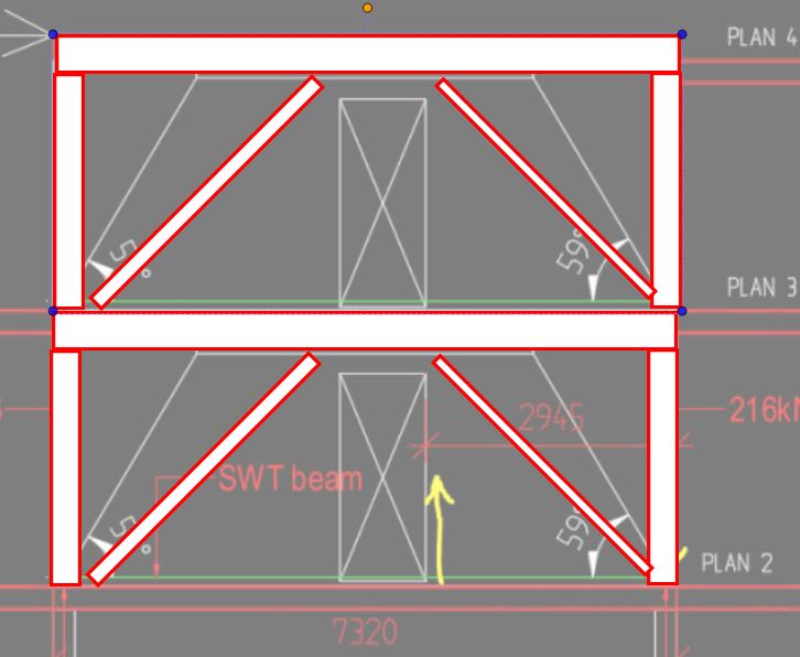
I have lookup and found a simplified loading system for designing coupled shear walls, Figure 3 and it shows overturning moments at the base of the walls (M1 and M2). At this point I feel really confused. How should I take care of M1 and M2 when the wall and the beam are not integrated for vertical load? Especially for M2, it creates tension of right edge of the door, how can I neutralize that tension when my compression force is already directed to the column head through a diagonal strut. Please find attached the file containing figures stated above.
Thank you so much in advance for any suggestion.



 https://files.engineering.com/getfile.aspx?folder=11dc9e12-d37e-4e07-a439-603311d652fa&file=Figure_file.docx
Replies continue below

Recommended for you

Any chance your boss was suggesting strut and tie modelling (STM) for gravity loads rather than lateral / shear wall? You've got a problem there too but, at least in that instance, I can see how STM might be your solution. Although, even at that, you might have trouble at your nodes connecting the struts to the ties as they may not have much to bear on.

C01_ipwksr.jpg
 
dik said:
The OPs situation is not uncommon because corridor openings above often don't accommodate parking drive isles below...
I've seen this done with RC walls in seismic areas and I can not figure out how such a system can withstand seismic actions... Any explanations on how force reduction factors would be defined in such a system, or how energy would be dissipated?


On topic, could you make the whole thing a frame with a light infill (7 meters seems like a reasonable span)?
Or maybe move the walls to a span where they can go down to the foundation?

 
@KootK
When you said imbalances in gravity load, did you mean wind load will cause the gravity load between both wall pier unequal? The sketch you made about the missing supports on the each side of door was right, especially on the left side where we have compression as we think that beam is not stiff enough so we try to avoid having compression there. As a result, we have been thinking that all horizontal force will travel axially through the couple beams to the right pier. Then a compression component of the base moment will be at the right column head and if we have enough gravity weight on that pier, it should prevent the right edge of the door from lifting.

By the way, the vertical loading conditions I showed in my first attachment are no longer valid. Eurocode recently changes how load cases shall be combined. When it comes to checking stability, only dead loads can be considered in providing stability. Thinking that the right pier taking all lateral forces, the base moment and couple forces are as followed:

Mo = 73.5kN*6.46m+45kN*3.240m =620 kN*m (Overturning moment)
T/C = Mo/2.945m = 210 kN
Mr = 197kN*2.945m*0.5= 290 kN*m (Resisting moment on the right pier) much less than Mo

I am not sure if my calculation is right. In case it is, it seems like the right edge of the door will lift so bad.

System_with_critical_load_case_y0ju3l.png
 

The one mentioned is far more complex than the OP...


I'm missing something, then...

Rather than think climate change and the corona virus as science, think of it as the wrath of God. Feel any better?

-Dik
 
@hardbutmild
I am working Sweden so we don't have seismic action but I can guess that this system could be unpopular in the country where seismic actions concerned.
While we don't consider seismic actions, we have to deal with improper structural system and heavy snow instead.
 
Yeah, I figured seismic wasn't a consideration in your case, I just wanted to ask others what they think about it.

But how about using a frame? It seems like a valid alternative if I'm not missing something.
 
Non-seismic but high wind, I believe.
 
OP said:
When you said imbalances in gravity load, did you mean wind load will cause the gravity load between both wall pier unequal?

No, I'd simply meant that even a non-uniform, gravity line load on the wall will work the coupling beams some.

hardbutmild said:
...I just wanted to ask others what they think about it.

It would be nuts for high seismic. Energy would be dissipated by obliterating the coupling beams, the wall ends punching through the floor decks, and then possible collapse or redistribution to other, unintended sources of lateral resistance. ASCE7 has for reduction and amplification factors for discontinuous shear walls but I'm pretty sure that it's assumed that there's still something stiff under the boundary elements of those shear walls.

hardbutmild said:
But how about using a frame? It seems like a valid alternative if I'm not missing something.

Absolutely if the numbers worked. One could also use a much stiffer eccentrically braced frame as shown below. This is sort of what the precast walls would be turning into with a coupling beam. Both steel frame options would involve the introduction of stiff floor level girders which don't currently exist though.

C01_liouxl.jpg
 
dik said:
I'm missing something, then...

All I am getting at is that:

1) there needs to be something stiff beneath the shear walls where the blue arrows are shown below in order for the shear wall system to be viable and;

2) #1 is almost certainly true whether the shear walls are connected by upper level coupling beam or not.

You agree with that do you not? As it stands, there is nothing stuff under the the ends of the shear walls that abut the door.

C01_zjolwn.jpg
 
KootK said:
but I'm pretty sure that it's assumed that there's still something stiff under the boundary elements of those shear walls.
I agree. Somehow this can be lost because the code is not always exact. I'd argue that even adding columns under the walls would not behave nicely during an earthquake and that boundary elements wouldn't be activated usually, but that's for another thread perhaps.

I was somehow thinking of precast RC frames (H frames for example) since the rest of the structure seems to be precast... I didn't realize that OP has a very shallow beam height.
Definitely not a good system if that's the case.
 
In my own city, you'll see a lot of this from the 60's and 70's which is not entirely dissimilar from what we've been discussing. Unfortunately, it's exactly this kind of thing that winds up in the PowerPoint presentations after earthquakes in Chile etc.

C01_fg4acq.jpg
 
Thinking simple, can the door be adjusted to the other side of the end column.

I'd just try some sort of EBF as Kootk noted. That's what I thought of as soon as I opened the thread.
 
@Kootk,
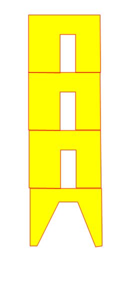
I like your yellow stacked walls sketch. It seems to be a simpler and nice way to look my problem.
 
Sandychan said:
I like your yellow stacked walls sketch. It seems to be a simpler and nice way to look my problem.

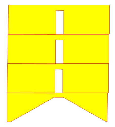
I'm glad, just don't take it as a design recommendation. Your proportions look a whole lot more like this. And proportions matter.

C01_or8f15.jpg
 
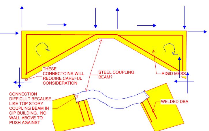
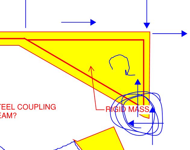
Attempting so suss out the mechanics of the above, I see something like this. I suppose that it actually would be fairly stiff if the coupling beam and difficult connections could be made to work. Again, this has a lot in common with a steel EBF.

C01_abcwqb.jpg
 
Were you to attempt to make a go of that load path, I feel that these connections would warrant very careful consideration. When a coupled shear wall system lands on something stiff, you've got a lot more space over which to deal with your localized joint stresses. That's part of the rub with not having something stiff below the walls. The only thing you've got that's worth a damn at that location is your columns.

c02_brqqzy.jpg
 
Status
Not open for further replies.

Part and Inventory Search

Sponsor