Continue to Site

Eng-Tips is the largest engineering community on the Internet

Intelligent Work Forums for Engineering Professionals

  • Congratulations waross on being selected by the Eng-Tips community for having the most helpful posts in the forums last week. Way to Go!

shearing of material 1

Status
Not open for further replies.

SpiritHunter

Mechanical
Mar 3, 2016
2
Hi,

Need some help with the shearing of material.

after welding of the material (S275) onto a plane, a force along the area of 150mm x 12mm

here, we would like to know
1. what's the force required before the structural fail.

2. the force required before the welding fail.
(weld using standard 6013 rod)

Thanks
 
 http://files.engineering.com/getfile.aspx?folder=43bda8e0-ec34-43f7-8c27-f5e494df624e&file=Km_0(1).jpg
Replies continue below

Recommended for you

Hello,

you forward EN material, so you probably have a job in the metric part of the world.. and you design under EC 3?
There, then, to get to an answer it's necessary to distinguish
- ruling load combinations (common / extraordinary)
- load nature (static / variable)
- type of application (type of building, vehicle loads, ..)
BTW, for the shear strength of a S275 with a fy of 275 N/mm² fy needs to be divided by sqrt(3).

Regards
R.


Hi, thanks for your information.
I guess it would be wise to lay out my application.

What we are doing is actually something like a micro pile.
there is a driver on top which have the force transfer via that 4 little plate which is welded onto the pipe.

At the field, we were told that the 4 plate that welded onto the pipe actually shear off.

So, now it's back to the drawing board so that we could know
1) the force that the little plate could hold before shearing.
2) if the welding could hold such force.

What's the issue with me is that i did not came from Mechanical background, so i am still stuck after going through the net about shearing.

Your assist on this issue is much appreciated.
 
 http://files.engineering.com/getfile.aspx?folder=26930667-8287-4af7-a52c-a24597338f78&file=Km_2.jpg
Hi Spirithunter

Firstly we need to know the size of the weld that the blocks are welded to the tube, then the next problem is that it will be impossible to weld four lugs onto a tube with such precision that the torque will be shared equally across the four.
It's more probable that only one lug is taking the entire torque and at best you might have two lugs taking the whole torque.

If the driving lugs are operated frequently the design of the driver should be analysed from a fatigue point of view.

“Do not worry about your problems with mathematics, I assure you mine are far greater.” Albert Einstein
 
Can you post some pictures of the "sheared off" plates and pipe?
For instance, showing clearly if the "shearing" goes through the weld, the plate, or the pipe.
Also, some pictures of the preparation of the plates before being welded, the fit up between the plates and pipes, and several of the finish welded plate/pipe assemblies.

As asked by others, details about the size and type of weld are needed.

When welding the plates to the pipe, is fixturing used to assure the consistent position and alignment of the plates? What is the tolerance on plate positioning, and the drive lugs of the coupling.
I'm guessing it is likely that only a portion of each plate is in contact with the drive coupling

Is the pipe rotated during the weld process, so each plate's welds are made in the horizontal position? Or, are some welds made out of position ( vertical or overhead).

Also, please provide pictures of the driving coupling, to see how it engages the welded plates, yet still misses the welds.

How thick is the pipe wall?

How do you inspect the finished welds? Is any non-destructive testing done of each finished weld?
Are multiple passes used on each edge of the plate?
Have your welders made representative test coupons and submitted them for some destructive testing?

6013 is generally considered a "fast freeze" electrode with moderate "penetration", often recommended for sheet metal work. There may be other electrodes better suited to making secure welds on these thick parts subjected to heavy loading.
 
Drawing2_Model_1_zkskfq.png

Hello SH,
From your input:
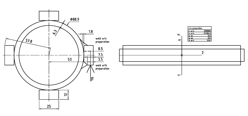
At M=20 kNm, if divided by 4*56 kN, you assumed the acting radius to be equal to the dia. of the pipe. But you need to relate the radius to the application point of the force onto the plates, so F imo should be 20/(4*0.053)=94,3 kN.
If welded w/o preparation the plate would have an important gap to the pipe, this should be avoided --> Assumed weld preparation as drawn, a weld to be 4.5 mm. Shear for one plate would arrive at approx. 63 N/mm². Assuming applicability for your utilization of standard FEM 2.132 (conveying machinery), the permitted statical shear stress at fillet welds for common / main loads is approx. 275/235*113 = 132 N/mm². Concluding: At least 2 of the 4 plates need to be load bearing.
Imo bending action should not be neglected, to the effect of a von-Mises stress of approx. 129 N/mm², to the same effect as said above.
Yes, you could have a stronger pipe than that, but with thicker walls + thicker welds, the loadbearing capac. of the fillet weld shall decrease too. Limit: t. b. sought / t. b. clarified.
However, if your load is rather cyclic / alternating, fatigue strength limits would apply, these being drastically lower than those mentioned above.
Now, as desertfox & Tmoose point out, there's little probability that with a welded design the plates shall arrive at an equal distribution of forces.
Alternatives:
- to manufacture the item from a dia. 120 mm block material of sufficient strength, and to tune size, shape + position tolerances of the driver and the mating hub
- to use a keyed / splined shaft profile
My request:
For this issue, please seek the support of a mechanical engineer who could responsibly design the drive considering all (unknown to us here) parameters. I gather there's more to it than the above input.
Regards
R.

9.3. ambiguity deleted
 
You are driving these piles by impacting on the lugs? This is a much different analysis.
 
@ Tmoose: Thanks for these pictures! --> *

@ OP: Could you pls. give us some pictures of the failed item? How are you proceeding? Thank you in advance for sharing these data!
 
I did solve a problem like this in past. My calculations were fro fillet weld. I have calculated it with respect to the fillet size and area required to be welded.
 
Status
Not open for further replies.

Part and Inventory Search

Sponsor