Eng-Tips is the largest engineering community on the Internet

Intelligent Work Forums for Engineering Professionals

Sheet Metal Part GDT

Status
Not open for further replies.

nmine

Mechanical
Jul 7, 2023
5
0
0
US
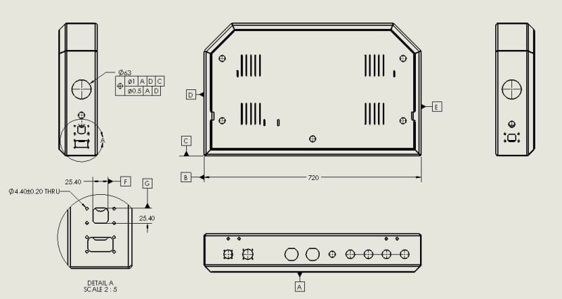
I have a large sheet metal enclosure base that has lots of panel mount connector holes. How do you go about applying GDT when one datum setup will not work for all of the different cutouts (for example bolt pattern around a larger connector cutout or a hole being perpendicular to a surface that is not a datum)? It would be a laser and bent part and it seems that relaying everything back to one datum setup would be hard to manage...Any advice?

Enclosure_vlmbvy.jpg
 
Replies continue below

Recommended for you

A single datum reference frame is only required when all features that reference it are locked into position and orientation to each other relative to the matching frame of reference in the assembly.

That is unlikely to be your case here.

Be aware that using the individual faces as datum features, being small, can magnify orientation if the large bottom face is used as a secondary or tertiary datum feature leading to location reporting problems.

Example, if there is 0.1 degree of allowed angle between the side and the bottom, using the side as primary will see a shift over a 10 inch bottom of 0.017 inch shift between the 0 degree and the 0.1 degree cases; that can be the equivalent of a 0.034 diametral position tolerance change and can easily affect the acceptance of the part.

A typical solution is to use the bottom surface as the primary datum reference for all the horizontal holes and the perpendicular face as the secondary datum reference to minimize this unwanted shift. The result may be a perpendicularity error of 0.1 degrees; for 0.030 thick sheet metal that resolves to 0.00005236 inches.

Since the holes are likely punched in the flat, the vertical direction and horizontal directions may have unequal variation and so a composite bi-directional position tolerance might be useful.
 
Hi Dave,

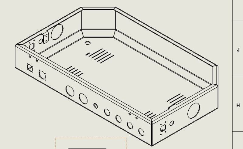
Thanks for the reply. So is the setup below what you mean (63 dia dim)? Also how would you relate the bolt holes to their cutout in detail A?

Enlcosure_2_daylxf.jpg
 
That reference for the 63 dia dim hole would better be [A|C].

The composite would only apply to multiple holes as it is to restrain multiple features at the same time.

For the square hole, the little holes surrounding it are locked into position and orientation to each other relative to the connector - it will mount to that face (primary) and the width and height of it limit the location of the connector. Since there is more than one of the little holes surrounding the square hole, the little hole location tolerance can use a composite feature control frame.
 
My guess is that the connectors are floating on the sidewalls. If that's the case their position may not be that critical. What would be more critical is the location of the mounting holes in relation to the connector cutout. The connectors probably have a datasheet that may show tolerances and you can use that for a tolerance stackup to see what kind of hole positions you can get away with. Once you have that data I think you can use the sidewalls as a primary datum for the respective connector holes, the connector hole itself as secondary, and the bottom surface as tertiary.
 
Maybe there are connectors hard soldered to a circuit board; obviously not all of them in the case or installation would not be easy, but along the largest formed face.

It always depends on everything that assembles together; answers when information is lacking is a problem.
 
Status
Not open for further replies.
Back
Top