Continue to Site

Eng-Tips is the largest engineering community on the Internet

Intelligent Work Forums for Engineering Professionals

  • Congratulations KootK on being selected by the Eng-Tips community for having the most helpful posts in the forums last week. Way to Go!

Sheet Metal part with counter sink holes.

Status
Not open for further replies.

BEAEROHEAD

Mechanical
Nov 1, 2007
75
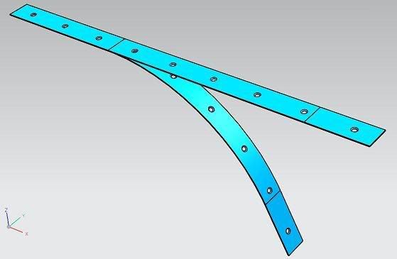
NX5 Sheet Metal Function: I have a curved part that has countersunk holes in it. When I create a flat solid of it only part of the hole translates. Any thoughts on what causes this? (see attached)
 
Replies continue below

Recommended for you

Wow ... I have never seem anything like that before.

Maybe start with a flat piece and then bend it to get what you want. It has been a while since I worked with sheet metal, but I am almost certain there is a way to do that.
 
This is beyond the capability of NX Sheet Metal, at least in NX 5. However in NX 6 this works fine, but there are still some issues that you should be aware of as it will effect the results that you get.

You have to understand that NX Sheet Metal tries to create a model based on what it would look like AFTER it's formed, and when you add a feature which can be flattened, the feature carries with it the geometric data of what it will look like flattened. So you have to approach using it in terms of how and when would you be performing certain manufacturing steps. For example, these countersunk holes, are they going to be 'manufactured' (added) to the sheetmetal part AFTER it has been formed, or to the flat stock BEFORE it's formed? If they are being added before it's formed and yet you still want to see them both in the formed and unformed state, you will need to learn to use the 'Unbend' and 'Rebend' functions to emulate the manufacturing workflow (please don't confuse 'Unbend' with 'Flat Solid' as these functions are intended to address two different situations). So in the case of holes which are added in the flattened state before it's formed, you can use the 'Unbend' tool to 'flatten' the solid, then add you holes and then use 'Rebend' to form it back to it's 'original' formed shape and the holes will inherit the proper shape of a hole which was there before it was formed, whereas adding a hole to the already formed part would be like actually drilling a hole in the finished part, which might be what your intended manufacturing workflow will be.

However, from a design point of view, one of the advantages of following the 'Unbend' - add the holes - 'Rebend', approach is that it will allow you to MOVE a hole from say the curved portion of a sheet metal part to an adjoining flat section and the model will update correctly. However, if you place the holes on the model while in the formed state, they are linked to the shape and extents of that face and would behave exactly as if you moved the finished part in the drill press when changing the location of where the hole is to be drilled.

Anyway, I hope you get the point, but for now you have to add the countersink (probably using a Chamfer) to the 'Flat Solid' in order to at least get close to what you want. It's either that or upgrade to NX 6 and model it correctly.

John R. Baker, P.E.
Product 'Evangelist'
Product Design Solutions
Siemens PLM Software Inc.
Cypress, CA

To an Engineer, the glass is twice as big as it needs to be.
 
To jerry1423 : Tried that no dice.
To JohnRBaker : Used bend and unbend. same thing.
Thanks for comments.
 
Yes, as I said, this was beyond the scope of NX 5, but it does work in NX 6, as shown below:

Sheet_Metal_bend_with_ctsk-holes-sm.jpg


John R. Baker, P.E.
Product 'Evangelist'
Product Design Solutions
Siemens PLM Software Inc.
Cypress, CA

To an Engineer, the glass is twice as big as it needs to be.
 
Status
Not open for further replies.

Part and Inventory Search

Sponsor