Continue to Site

Eng-Tips is the largest engineering community on the Internet

Intelligent Work Forums for Engineering Professionals

  • Congratulations SSS148 on being selected by the Eng-Tips community for having the most helpful posts in the forums last week. Way to Go!

Sheet piling waler system design

Status
Not open for further replies.

BridgeDude1487

Structural
Mar 10, 2016
7
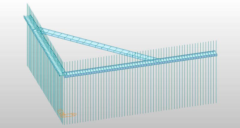
I am designing an unusual waler system for an L shaped sheet pile wall. The waler system consists of two beams welded along the sheet piles near the top, one on each leg of the "L". There is a corner brace that spans between the two beams, making each beam what I would call "simply supported with a cantilevered overhang". The beams welded on the sheet piles will support the anchor force and be in flexure. The corner brace will be in compression. Determining the moments in the support beams is easy enough--they can be modeled as a beam on two supports with an overhang. The compression in the corner brace is the issue.

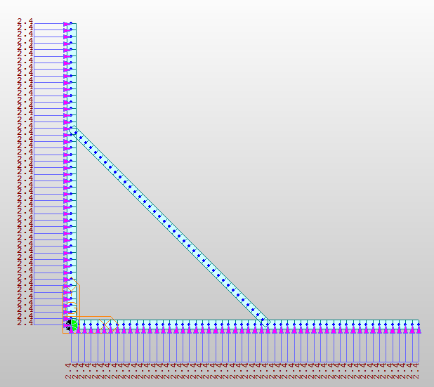
I attempted to model this in an FEA program as a simple frame, but in its current state, it's underconstrained. The unbalanced loading (as a result of the difference in length of the sides of the L) causes the frame to spin. If I fix one of the joints between a waler and the corner brace, the reaction force is all absorbed by the node fixity rather than the brace.

Any way to go about modeling this or simplifying it better, or tips on where else I can constrain my model?

If not, can I just run two simple beam analyses for each waler and design the brace for the largest reaction at the brace?

A pic of the basic layout for reference (without supports of loads shown):
walersystem_utoitn.png


Frame model:
walerframe_niqphf.png
 
Replies continue below

Recommended for you

It seems to me that your frame model is incomplete. The shear strength of the soil along each leg of the L helps prevent one leg from wanting to move up and the other leg from wanting to move toward the right. As you have drawn the frame model, it is sitting out in space with unbalance forces in the X and Y directions. These types of sheeting walls aren't usually designed using FEA. It is always a tough call to determine how long a wale needs to run along a leg in order to prevent that leg from pushing longitudinally. Sum the applied forces in the X and Y directions. They add up significantly. Something needs to resist approximately 50 ea. x 2.4 kips(unit?) = 120 kips(unit?) along each leg.

 
PEinc has the right of this I believe. Throw in an axial only restraint at the cantilevered ends of the whalers to model the soil shear strength that he mentioned.

I like to debate structural engineering theory -- a lot. If I challenge you on something, know that I'm doing so because I respect your opinion enough to either change it or adopt it.
 
Yes, my model is incomplete in its current state and I'm curious if anyone knows the best way to complete it (i.e. what to restrain). As I said in my original post, in its current state, the waler system obviously just rotates about the corner because of the force imbalance. Also, the sheeting is not being designed using FEA, that was done using CWALSHT. The first picture is simply for reference (although I did attempt modeling the system that way, and it didn't work right). I pulled the anchor force from CWALSHT (2.4 klf). The wale runs along the entire length of each leg. Imagine a SP wall behind the wales and a building on the right and top.

KootK - I've actually tried adding axial restraint to the walers (representing the weld to the sheeting) and I still get an unconstrained model and massive deflections. I need to somehow model the effect of the soil on the back sides of the wall restraining the walers from moving in that direction. The soil is really the complicating factor in all this.
 
OP said:
If I fix one of the joints between a waler and the corner brace, the reaction force is all absorbed by the node fixity rather than the brace.

This method should work and is appropriate in opinion. You would add an XY translational pin to one end of the brace, get your numbers, and then move the pin to the other end of the brace. Or, if you just want the worst case result, just pin the end of the brace where the cantilever is longest.

I like to debate structural engineering theory -- a lot. If I challenge you on something, know that I'm doing so because I respect your opinion enough to either change it or adopt it.
 
KootK - Thanks. That method does seem like the best way I can think of to do it. But my results give the worst case when the shorter cantilever brace end is pinned, because the longer end with more force is causing a higher compression force.
 
Yup, that makes sense.

I like to debate structural engineering theory -- a lot. If I challenge you on something, know that I'm doing so because I respect your opinion enough to either change it or adopt it.
 
Status
Not open for further replies.

Part and Inventory Search

Sponsor