BridgeDude1487
Structural
- Mar 10, 2016
- 7
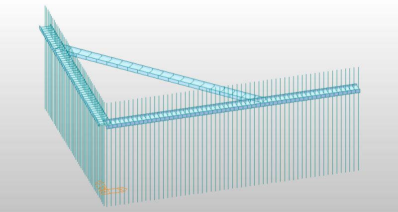
I am designing an unusual waler system for an L shaped sheet pile wall. The waler system consists of two beams welded along the sheet piles near the top, one on each leg of the "L". There is a corner brace that spans between the two beams, making each beam what I would call "simply supported with a cantilevered overhang". The beams welded on the sheet piles will support the anchor force and be in flexure. The corner brace will be in compression. Determining the moments in the support beams is easy enough--they can be modeled as a beam on two supports with an overhang. The compression in the corner brace is the issue.
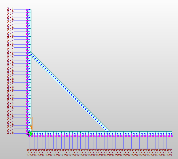
I attempted to model this in an FEA program as a simple frame, but in its current state, it's underconstrained. The unbalanced loading (as a result of the difference in length of the sides of the L) causes the frame to spin. If I fix one of the joints between a waler and the corner brace, the reaction force is all absorbed by the node fixity rather than the brace.
Any way to go about modeling this or simplifying it better, or tips on where else I can constrain my model?
If not, can I just run two simple beam analyses for each waler and design the brace for the largest reaction at the brace?
A pic of the basic layout for reference (without supports of loads shown):

Frame model:

I attempted to model this in an FEA program as a simple frame, but in its current state, it's underconstrained. The unbalanced loading (as a result of the difference in length of the sides of the L) causes the frame to spin. If I fix one of the joints between a waler and the corner brace, the reaction force is all absorbed by the node fixity rather than the brace.
Any way to go about modeling this or simplifying it better, or tips on where else I can constrain my model?
If not, can I just run two simple beam analyses for each waler and design the brace for the largest reaction at the brace?
A pic of the basic layout for reference (without supports of loads shown):

Frame model:

