FEAMonkey
Aerospace
- Nov 17, 2019
- 15
Hi Everyone,
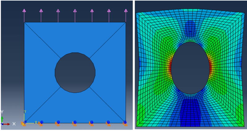
I have modelled a 3D plate using shell elements in Abaqus. I have applied a fixture to the bottom edge and load on the top edge of the plate. The setup and the result of the analysis:

As you can see, the top edge of the plate where the load is applied is curved in the direction of the load. In reality, the load is applied by a big clamp which pulls the whole edge up. Therefore, in the simulation result my deformed shape should show straight top and bottom edges.
How can I apply the load in the appropriate way?
Thanks for your help.
I have modelled a 3D plate using shell elements in Abaqus. I have applied a fixture to the bottom edge and load on the top edge of the plate. The setup and the result of the analysis:

As you can see, the top edge of the plate where the load is applied is curved in the direction of the load. In reality, the load is applied by a big clamp which pulls the whole edge up. Therefore, in the simulation result my deformed shape should show straight top and bottom edges.
How can I apply the load in the appropriate way?
Thanks for your help.
