Continue to Site

Eng-Tips is the largest engineering community on the Internet

Intelligent Work Forums for Engineering Professionals

  • Congratulations KootK on being selected by the Eng-Tips community for having the most helpful posts in the forums last week. Way to Go!

Shell with UG-34 (f) flat head extended as Skirt ASME Sec VIII Div-1

Status
Not open for further replies.

cak4Engg

Petroleum
Jun 13, 2015
19
Dear All,

In a heat exchanger, in order to keep the exchanger height as min. as possible, I have proposed the following config.
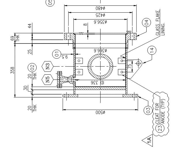
Shell_with_flat_head_extended_as_skirt_gapsga.png


Where the Shell course (Item-01) with a UG-34(f) flat head (Item-02) is extended and the base plate(Item-03) is welded to it.
one of my colleagues has a comment that Since this joint configuration is nowhere addressed in the code, we need to perform FEA as per u2(g) evaluate the said configuration.

What do you guys think about this, is it acceptable as per code? do we have to perform FEA?

I would really appreciate your input.

with regards
 
Replies continue below

Recommended for you

Hi cak4engg,

if you need to maintain minimum height for your design , then instead of extending Shell course is it possible for you to use Weld neck flange or long weld neck flange for item 4 ?

 
I agree with your colleague - what were you planning for the lower tubesheet - an internal fillet?
Put a step on both sides of the lower tubesheet and weld as per an NEN design (Fig UW-13.2(c)(d)or (e-2)).
 
cak4Engg, the proposed design is not prohibited under Sec VIII, Div 1, therefore it is permitted. Design rules exist for all portions of the channel except the base ring, which can be designed per a handbook such as Moss, etc. The difficulty is going to be the influence of stresses on the segment of shell between the head and base ring, which must be accounted for in some way, of which FEA is one.

Regards,

Mike

The problem with sloppy work is that the supply FAR EXCEEDS the demand
 
Thank you all for your valuable input.

@SnTMan has got the question right, After a few discussion and going through the code, I have also concluded to the same.
The segment of shell between the head and base ring need to evaluated using FEA. Non-Mandatory Appendix G(5)(b) gives more insight into the same.

Quote

"When the skirt is attached below the head tangent line, localized stresses are introduced in proportion to the component of the skirt reaction which is normal to the head surface at the point of attachment; when the mean diameter of skirt and shell approximately coincide and [highlight #FCE94F]a generous knuckle radius[/highlight][/color] used (e.g., a 2:1 ellipsoidal head), the localized stresses are minimized and are not considered objectionable. In other cases, [highlight #FCE94F]an investigation of local effects may be warranted depending on the magnitude of the loading, location of skirt attachment[/highlight], etc., and an additional thickness of vessel wall or compression rings may be necessary."

UnQoute
 
Status
Not open for further replies.

Part and Inventory Search

Sponsor