Continue to Site

Eng-Tips is the largest engineering community on the Internet

Intelligent Work Forums for Engineering Professionals

  • Congratulations KootK on being selected by the Eng-Tips community for having the most helpful posts in the forums last week. Way to Go!

Shock loading a VFD driven motor coupled to high-inertia load 1

Status
Not open for further replies.

2bu3bdullah

Electrical
Oct 8, 2016
4
Hi,

Application is: Crude Oil Separation
VFD: Rockwell PowerFlex 753 (480V 60Hz Input, 52A/40HP 460V Output)
Motor: ABB 3-Phase Squirrel Cage Motor (480V Delta, 30kW, 60Hz, 1788 r/min, Class F, Duty S1)
Load: Centrifugal Separator connected to the motor through gearbox (1800 rpm to 4800rpm)

Using "Sensorless Vector Control" mode (Induction SV), we have success starting the motor from standstill or Fly starting from any speed (Even at low speeds).

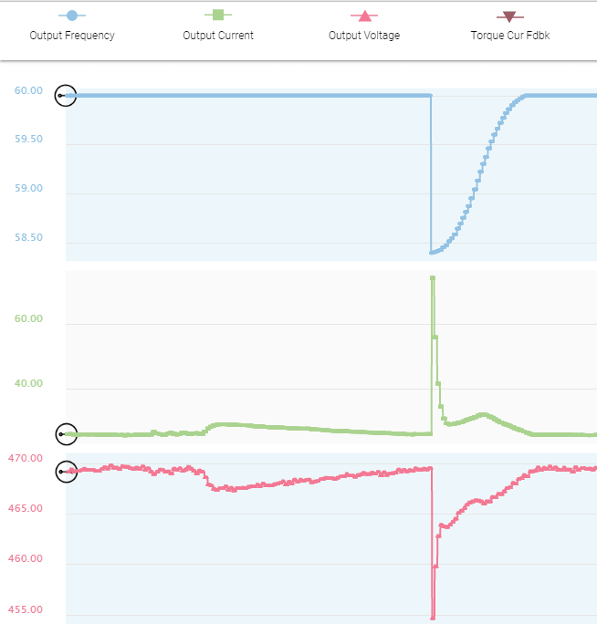
The problem occurs during the cleaning of the Separator when discharging using high pressure water, this is acting as a shock load to the motor and the VFD is limiting the current by decreasing the output frequency which causes at least about 45 rpm speed reduction (We tested using water but if crude oil is used speed is expected to decrease > 150rpm).

The current limit is set to 78A which is the rated VFD overload current (78A for 3 Seconds), if the current limit is reduced the speed reduction will be more (~ 500 rpm) which is not accepted.

We are afraid that the VFD may trip if the shock loading is increased (current will exceed 78A for more than 3 seconds)
Any ideas how to enhance the performance of the VFD during the shock loading ?
Capture-1_Third_and_Fourth_Disch_nxzqfm.png
 
Replies continue below

Recommended for you

If the VFD is limited to 78A for 3 seconds and you need more than that then sorry, there is nothing you can do as the VFD is hard limited in its firmware to trip-out on that overload.

The simple solution is to step up the VFD to the next higher rating.


Keith Cress
kcress -
 
Be aware that you may solve the problem but destroy the motor.

Bill
--------------------
"Why not the best?"
Jimmy Carter
 
First off, a 52A drive is 40HP Normal Duty, meaning pumps and fans. It is not rated for overload duty of any reasonable amount; 110% for 60sec, 150% for 2 sec (IIRC). At the very least you would need a Heavy Duty rated drive. Over sizing More than that it would help the drive, but understand that the motor is ultimately your limiting factor.


" We are all here on earth to help others; what on earth the others are here for I don't know." -- W. H. Auden
 
OK, the VFD rating may be less than required but the motor most of the time is running at normal duty (~25A at full speed), unless accelerating. The overload only occurs for less than 2 seconds during the shock loading.

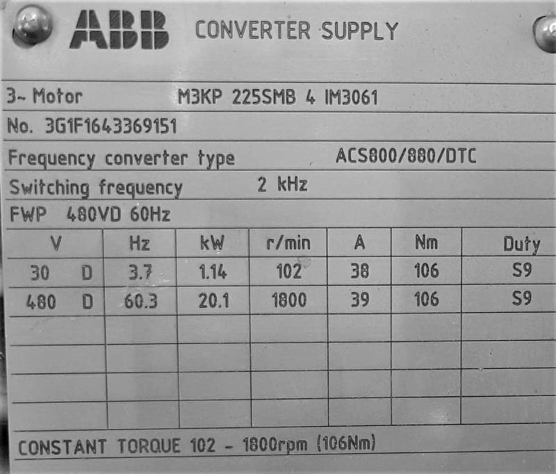
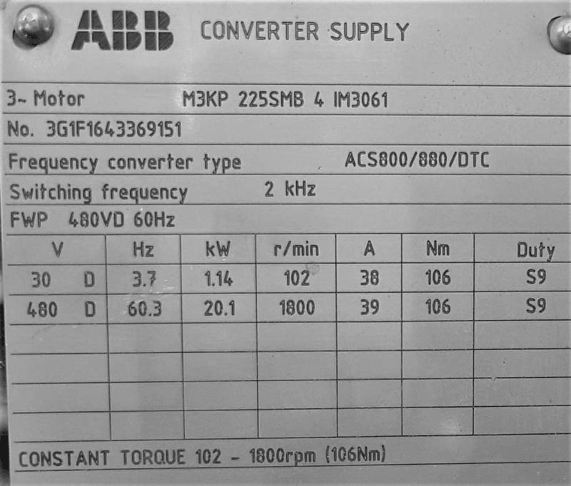
The motor manufacturer ABB recommends its drive ACS880/ACS800 with DTC (Direct Torque Control) for driving the motor. But this is not available as the MCC is already installed and powered.

So, can we have a similar performance of the the ABB DTC using the AB PowerFlex 753 ? or we have nothing to do with the drive parameters and the issue is hardware limitation ?

ABB_DTC_sww8pu.jpg


Thanks
 
Is the requirement during cleaning the absolute rpm or the drop in rpm ?

If the first is the case you may solve the issue by increasing speed prior to cleaning.
 
The motor slip at full load is 12 rpm. (1800 RPM - 1788 RPM)
A drop of 45 RPM is a slip of 45 RPM + 12 RPM. Almost 500% and certainly over 400%.
This is complicated by the drop in frequency, however 78 Amps on a 52 Amp rated motor is about 150% of rated motor current.
This from an inverter that seems to be rated for 39 Amps.
78 Amps is 200% of the inverter rating.
If the motor was to draw 104 Amps at 60 Hz, the slip would be about 24 RPM. (12 RPM + 12 RPM.)
At 130 Amps, 250% of FLA, the slip may increase to 30 RPM but you may be approaching pullout torque and things become non-linear.
It looks as if your VFD is undersized for an undersized motor.
Note: My estimates are based on a solid 60 Hz supply.
With a larger VFD you can increase the motor current and the torque.
You will not be able to develop more than pull-out torque with any current.
Your pull-out limit depends on the motor design but 250% may be a reasonable estimate.
I suggest that the best that that motor will do is about 25 RPM to 30 RPM drop in speed.
electricuwe's suggestion may be a quick and painless fix.
BUT:
That is depending on linear loading.
I suspect that your torque/load curve may be non-linear, and similar to the loading curve of a centrifugal pump.
If that is the case, my estimates will be too low and you will need a bigger motor or else run over-speed.

Bill
--------------------
"Why not the best?"
Jimmy Carter
 
I have encountered the same issue in a completely different situation. Mechanical sizing standards unless they specifically say otherwise, are typically based on motors with conventional power supply situations. As long as the protection (fuses and motor overloads) do not trip it was called good.

With inverter drives protection is provided by drive parameters which really are hard limits. In this case your current increased to the torque limit - sometimes called max amps. The technician from Square D called this behavior Brick Walling.
Some options to consider are
[ul]
[li]Accept the behavior - viable if the results of your cleaning cycle are acceptable with the speed drop.[/li]
[li]Modify the mechanical system (expensive and sometimes impossible).[/li]
[li]Modify the drive parameters (in my case setting max amps to 200% worked).[/li]
[li]Higher power drive (assuming the centrifuge mfgr has made the motor selection, and has some history of acceptable performance).[/li]
[li]Replace the drive with a soft start, and bypass contactors. This is viable if the only speed you need to operate at is nominal 1800 r/m (60 Hz). There will still be some speed droop resulting from the shock loading during cleaning, but the motor will follow it's 60 hz torque curve, so the droop might be a bit less than observed with the drive.[/li]
[/ul]

Hope this helps
Fred
 
The drive appears to be undersized and is already at 200%.
Drive rated 39 Amps, limit 78 Amps.

Bill
--------------------
"Why not the best?"
Jimmy Carter
 
2bu3bdullah,
There is virtually no difference in the ABB drive vs the AB drive if you pick the wrong size. If you are going to get a different drive, get a larger PowerFlex drive.

Bill, the drive he has is rated for 52A, not sure where you are getting the 39A from. But it is 52A Normal Duty, aka “Variable Torque”, so as I described earlier it is not rated for overload conditions.


" We are all here on earth to help others; what on earth the others are here for I don't know." -- W. H. Auden
 
jraef & waross,
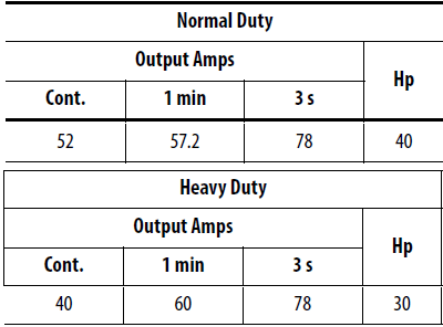
The drive is rated for heavy duty but at lower limits as below, and as you see the Heavy Duty (HD) and Normal Duty (ND) rating for short time overload is the same : 78A
VFD_Rating_cx1lxb.png


FacEngrPE,
Actually the drive is not tripping, we have by mistake performed one test with the drain valve closed and the drive didn't trip although the speed drop was about 500rpm at that case. But as you said it is still running and no trips.

On PowerFlex 750, if the drive detects that it is being overloaded, it will reduce the PWM frequency, and then reduce the current limit. These steps may allow the drive to continue running without faulting, but the output frequency and speed may also decrease.

For the current limit setting, the drive does not act on this value. Instead, all parameters related to overload are simply a user recommended max value for current limit.
 
Jeff said:
Bill, the drive he has is rated for 52A, not sure where you are getting the 39A from
2bu3bdullah (Electrical) (OP) 29 Nov 20 07:41 said:
My mistake.
I misunderstood the post.

Bill
--------------------
"Why not the best?"
Jimmy Carter
 
The HP ratings are just a numbers game. In your example, the drive always has the same thermal overload capacity. By playing the numbers game, the normal duty is capable of 78/52 = 150% continuous current for 3 seconds and the heavy duty is capable of 78/40 = 195% continuous current for 3 seconds. See the numbers game? If you use a bigger drive then you can get more current and more current = more torque = no speed reduction.

You need to follow this process;
- Figure out the torque you need to hold the speed constant.
- Figure out the amount of time you need that torque.
- Check the motor can produce the torque and what current is required for it to produce that torque.
- Pick a drive that can supply this current for the time the current is needed.
 
" Figure out the torque you need to hold the speed constant."
Pull out torque will limit the maximum available to about 200% to 250%, depending on the motor design.
They may need a larger motor as well as a larger drive.

Bill
--------------------
"Why not the best?"
Jimmy Carter
 
Yes Lionel.
I was pointing out that as well as picking a suitable drive, you may have to also pick a suitable motor.
Please consider my post complimentary to yours, not a contradiction.

Bill
--------------------
"Why not the best?"
Jimmy Carter
 
If you return back to the ABB converter performance data shared above, you will see that the drive and the motor can deliver constant torque 106Nm at speeds range from 102-1800rpm at about 39A output current.

So, for the drive (at Normal Duty) which can supply continuous 52A output current at full speed to the motor (FLA: 49.3A), can we say it can handle the torque required to withstand the shock load and the speed drop ?

I think the problem in my current configuration that it is set for variable torque and speed regulation, so if the motor reaches full speed the torque required to keep the motor at full speed is lower than that required for acceleration, and in return the output current is reduced to adapt for the lower torque requirement.

So, may be what we need is to configure the drive for torque control (Constant Torque) in Flux Vector mode instead of speed regulation, Danfoss says "Sensorless Flux Vector" can handle shock load better than other control modes (like VVC, SV, V/Hz).

I will try the above configuration and see if it can make difference.
 
If that nameplate is from the motor, then that is a 20kW motor, which makes it a 25HP, not 30kW (40HP) as you said in the first post. So if that is indeed what you have, then that drive is fine, it is a 30HP (22kW) Constant Torque rated drive.

But yes, the DEFAULT setting for the drive will be Normal Duty which provides a variable torque output curve, so you would have to change it to a Constant Torque output. So on a PowerFlex 753, you would change Parameter 306 from a zero to a 1.

You also have the option for Sensorless Vector Control (SVC) or, if you like, "Encoderless Flux Vector Control", which is similar but more ACCURATE in terms of providing torque more quickly, but does not provide MORE torque. By quickly, I mean that the response to a step change in load is going to be in a few radians as opposed to a few revolutions. In a high inertia load such as yours, that likely will make little difference. If you want to experiment with it though, P35 is where you change the control mode. If you want to try Encoderless FV mode, you set P35 to Induction FV mode, then you don't give it an encoder feedback. But you must pay attention to other factors, such as the gain on the feedback loop, compensation for cable capacitance etc. In addition, you will want to do a ROTATING autotune, not just the simple static one that you can use for SVC.

"Torque Control" is for when you want torque to be constant regardless of speed, like in a wider application where the speed is constantly changing because of changing diameters of the load, but you don't want too much or too little torque because you don't want to tear the material. That is NOT what you want here, because you have already established that a change in speed is undesirable. Leave it in Velocity mode.


" We are all here on earth to help others; what on earth the others are here for I don't know." -- W. H. Auden
 
I would likely try drive for torque control (Constant Torque) in Flux Vector mode also. Changing drive parameters is hugely less expensive than changing hardware. Flux vector + encoder feedback might improve performance a bit, but as the application does not need precision and requires adding the encoder, I would try this after other options.
Fred
 
Status
Not open for further replies.

Part and Inventory Search

Sponsor