Enable
Structural
- Jan 15, 2021
- 788
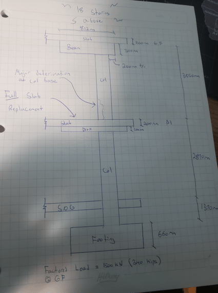
So here's the situation. P1 slab is being fully replaced in an underground parking garage. The slab abuts a 300mm x 600mm corner building column. This column is significantly deteriorated at its base and once the removal of the P1 slab occurs it is likely much of that column will come with it. Based on preliminary drilling at least half of the column is in questionable shape.
Thus the shoring needs to be designed to pickup the entirety of the column load in case the worst should happen. Problem being this is an occupied apartment complex and going above the ground floor level is a no-go.
The P1 column has a 812mm x 300mm beam above it plus a 200mm slab that can be used to transfer the vertical load to adjacent vertical shoring. But the factored loads are about 3x the shear capacity of these members so I need a way to transfer the load from the P1 column to my steel shoring structure (see loads below). I'm thinking a steel collar with post-installed anchors and taking the vertical shoring to the footing.
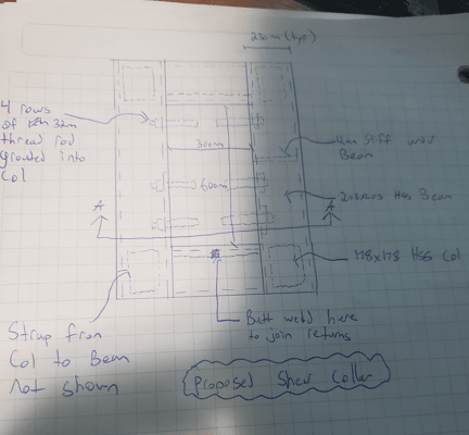
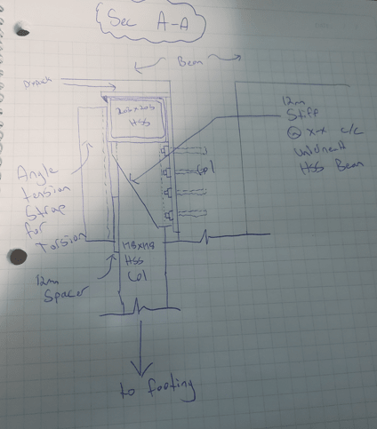
Below are some sketches of the elevation / proposed collar. It seems a bit clunky so before I go full monty and start to calc it all out I just wanted to get insight from the team to see if there is a better way to do this (that's why details on welds and such are sparse this is more conceptual at the moment). I'm assuming that the slab + beam will pick up their full shear capacities / transfer that to the vertical shoring, and so the collar anchorage is designed for the net (about 1000kN).
Engineering particulars:
fc = 20 mPa
factored load on column = 1500 kN
200mm ground floor slab with Vr = Vc = 230 kN
812mm x 300mm beam above P1 column with Vr = 237 kN = Vc + Vs
Here's the elevation sketch

Here's the plan of the collar

Here's section A-A

CWB (W47.1) Div 1 Fabricator
Temporary Works Design
Thus the shoring needs to be designed to pickup the entirety of the column load in case the worst should happen. Problem being this is an occupied apartment complex and going above the ground floor level is a no-go.
The P1 column has a 812mm x 300mm beam above it plus a 200mm slab that can be used to transfer the vertical load to adjacent vertical shoring. But the factored loads are about 3x the shear capacity of these members so I need a way to transfer the load from the P1 column to my steel shoring structure (see loads below). I'm thinking a steel collar with post-installed anchors and taking the vertical shoring to the footing.
Below are some sketches of the elevation / proposed collar. It seems a bit clunky so before I go full monty and start to calc it all out I just wanted to get insight from the team to see if there is a better way to do this (that's why details on welds and such are sparse this is more conceptual at the moment). I'm assuming that the slab + beam will pick up their full shear capacities / transfer that to the vertical shoring, and so the collar anchorage is designed for the net (about 1000kN).
Engineering particulars:
fc = 20 mPa
factored load on column = 1500 kN
200mm ground floor slab with Vr = Vc = 230 kN
812mm x 300mm beam above P1 column with Vr = 237 kN = Vc + Vs
Here's the elevation sketch

Here's the plan of the collar

Here's section A-A

CWB (W47.1) Div 1 Fabricator
Temporary Works Design
