Continue to Site

Eng-Tips is the largest engineering community on the Internet

Intelligent Work Forums for Engineering Professionals

  • Congratulations KootK on being selected by the Eng-Tips community for having the most helpful posts in the forums last week. Way to Go!

Shoring a cantilever slab 1

Status
Not open for further replies.

DeeMIA

Structural
Sep 19, 2018
5
Hello,

Looking for some out of the box ideas for this unique situation.

I am working on restoring the slab of a concrete framed parking facility of a high-rise residential building. It is a two-way slab with three bays in one direction, and 10 bays in the other direction. In the direction of the 3-bays, the two end bays are cantilevered. I encountered significant concrete delaminations along the column strips, top of slab, nearby the columns where the top steel should be developing. This situation occurs at various column strips throughout the structure, and also occurs at the same location on multiple levels. The parking facility is 9 levels. My worry is that during construction, the vibration for the chipping hammers will loosen up any bond that is left in the bars enough that it may cause a potential failure.

The ground level of the structure is a restaurant and a lobby space so shoring down to the slab on grade is not feasible. Traditional shoring down two levels to share the dead/live load of a particular level with other levels below is also not feasible everywhere as there are stretches that have delaminated concrete at a particular column strip at several levels below.

I have been contemplating a few options, the options I've thought about include:

1) Developing a triangular bracing frame to support the cantilevered slab and anchoring the frame to the column (could be costly if this has to be done at dozens of locations).
2) "Tying" all cantilevered slabs with post-tensioned cable so that they all react together. I am unsure about this one because although the slabs currently holds up to the service level dead and live loads, how can I prove that they will all act in unison to resist a slab that is trying to collapse if I don't know how much capacity I have left?
3) On a particular level (lowest preferred), drill through the column in the direction of the cantilever span, install reinforcement through the column and out to the cantilever, and cast a concrete wall. This would essentially create a very deep beam and transfer the loads to the column. The levels above the wall could then be shored traditionally.

I would like to hear if any of you have encountered this problem and how you resolved it. Or if you haven't encountered it, but you have some thoughts, that would be great as well. Thank you!
 
Replies continue below

Recommended for you

I'm in the category of just having some thoughts. Your #1 option seems to be the best approach for the following reason:

Redundancy. I assume each bracing frame will be independent of all the others.

I would not want to rely on concrete that is already in poor condition for load sharing (Option #2).

Option #3 sounds like the first step is to put additional load on existing structure (weight of the proposed concrete wall).

[idea]
[r2d2]
 
I agree with SRE.

Do you know anything about the structure other than that there is some spalling? Post-tensioned? Exposed to weather? Spans and thicknesses?

I know you just asked about shoring, but a better idea of the structure might result in better responses.
 
Thanks SRE and Hokie for the response.

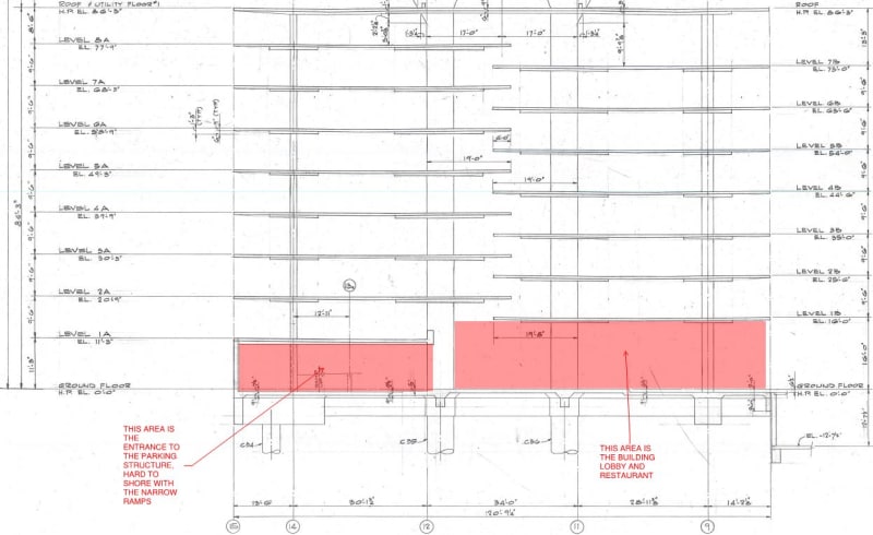
The structure is conventionally reinforced, two-way slab with drop panels. In the E-W direction (direction of the cantilevered slab) the reinforcement is typically laid out as one would expect a 2-way slab (column strips and middle strips). In the other direction, the reinforcement is actually evenly distributed. Off the top of my head, the cantilever spans approximately 2/3 of a vehicle length (10 feet) and only top steel is present. The center span is nearly 25 feet. I can confirm these tomorrow morning.

The structure is enclosed, but it is exposed to chlorides as vehicles bring in the road salts. The structure has been repaired in the past but it has likely been a decade since its last restoration effort; hence it is experiencing concrete delamination from corrosion of the top steel reinforcement in the E-W direction (cantilevers).

As I mentioned previously, the concern is on top steel debonding, which can also lead to some punching shear failures as well. Typically we observe delaminations behind the column at about the last 2-3 feet where the column strip top steel should be bonded and developing.

The ideal solution would be to implement a way that I would be able to set up shoring on the lower level (let's say between Levels 1 and 2 since ground level is inaccessible), then use that stable/supported slab to share/distribute the load on whatever floor the contractor is repairing immediately above.
 
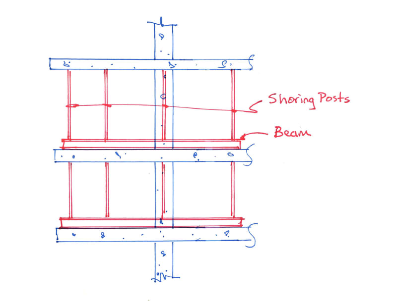
Maybe something like the attached could work. Kind of a typical shoring/re-shoring setup but with the addition of steel beams flat on the slab so the questionable slab doesn't have to do as much work.

shoring_jndkwd.jpg
 
CANPRO, that is an interesting layout, it would block a portion of the drive lanes but it may be manageable. My only concern with that design is that the span on the left hand side of your drawing would be reacting against a slab that does not have too much top steel to take care of the bending moment from the post shores. Below are images of the framing.

elevation_xd7tza.jpg


span_dqrr4d.jpg
 
DeeMIA, the concept would be to use the beams laying on top of the slab to take the negative bending out of the slab and reduce the demand on the top bars. The reaction of the steel beam on the slab, in line with the columns, would create positive bending in the slab, putting the bottom bars in tension. I would design this essentially the same as formwork and assume the slab has no capacity beyond the column line.
 
DeeMIA:
I too like your method #1 best. Except, on the lowest level to be repaired it will have to be treated a little differently. Since it is applied right at/on the E-W col. lines it might even work in some locations where level 1A must be repaired. Alternatively, install the frame system, btwn. levels 1&2, in the usual way to repair level 3A, and then install hanging rods to support level 2A for its repair. Use stl. rods, not post-tensioned cable for the hangers down through level 2A, because the cables or PT rods stretch too much before they are fully brought into play. Yes, this is expensive, but you didn’t cause the problem, you are trying to fix it in a practical, reasonable fashion. While you may have to do this several hundred times, you only need 10-15 sets of frames, because they can be moved to the next location as soon as the repair is sufficiently cured.

I would make my frames in two, mirror image, halves; one for the north side of the col. and the other for the south side. They would bolt/clamp around the col. to impart their horiz. reactions to the top/west face of the col. and a compressive force to the bot./east face of the col. The top members would have a separable beam at their tips, running N-S, and the depth of the col. drop panels. The top member, a tension and bending member might extend back into the center span so as to impart its horiz. reaction to the back of the drop panel, not the col. top. The diag. kicker (separable, pinned) would meet the top at about the drop panel east edge, and would meet the verts. at their reaction point on the east/bot. of the col. With some clever design and detailing these frames could be lifted (tipped up) into place on either side of each col., bolted/clamped to the col. and the tip beams installed (running N-S, how long?). Some shimming might be needed to bring the top beams to bear. The entire frame could then be loaded (rotated about the top, at the col.) with a small hydraulic jack and pressure gage at the base of the col., rotating the tip beam up, with some force(?), and shims would be dropped into the compression bearing arrangement at the col. base. A half dozen of these frames could be installed down the length of the bldg. by team 1, while team 2 does the same thing, on that fl., at the west col. line. The frames may not even have to be disassembled to move up a fl., since the are only about 9.5’ tall and 10-15’ long.

The trick is clever detail of these frames, of their installation sequence, and the slab repair sequence, and then the jumping of the frames to their next location in a couple weeks. While the upfront design and fab. doesn’t come free, it may be no more costly than other methods.
 
The relative stiffness of the beams vs. the slabs they are set on will likely still put the bulk of the load on the slab (and may certainly work). You may be able to use blocking to elevate the beams to create a platform - but handwork with members of a size large enough to be meaningful could be a challenge.

The comment about interrupting drive lanes was a challenge - my assumption would be this deck (or at least this area) would already be out of service with the damage described - if the goal is to keep parking cars while repairs are underway and keep the restaurant open, can the public be protected?


When we have provided shoring for similar situations, demoltion/recast,(more commonly when the edge of slab cantilevers well beyond at a level above), we would use an arrangement of members not too far off from what CANPRO notes, but blocked up at the column line or at the EOS or wherever the EOR and I can determine is the best place for the reaction and cantilever many small members with as far back of a hold down reaction as possible, making an outrigger style platform to work and shore from.


It could be possible to install a column hung shoring system or pair of beams at the columns adjacent to the cantilever and then cantilever beams in direct support of the slabs from the column line, with a backspan reaction within the structure. Enough capacity could probably be developed to limit deflections within reason, but my reasonable (1"), may not match your definition.

Rather than a slab panel, you would use the jacks and supporting headers (beams) to box around the available columns, then use other members to cantilever and support the repair area.

But the mention of punching shear failure makes me concerned with any process that does not find an alternate path to ground, if there really are concerns about losing connection to the slabs.
 
Status
Not open for further replies.

Part and Inventory Search

Sponsor