Continue to Site

Eng-Tips is the largest engineering community on the Internet

Intelligent Work Forums for Engineering Professionals

  • Congratulations KootK on being selected by the Eng-Tips community for having the most helpful posts in the forums last week. Way to Go!

Shoring Design - Connecting Props (post shores) to Girders (aluminum or wood beams) 5

Status
Not open for further replies.

Deener

Mechanical
Aug 30, 2018
48
Hi All,
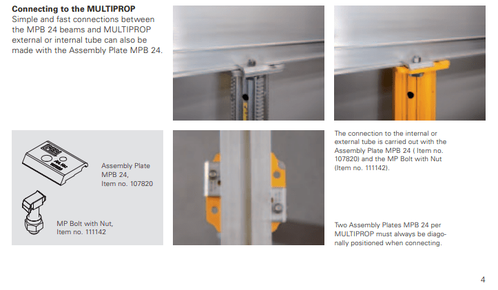
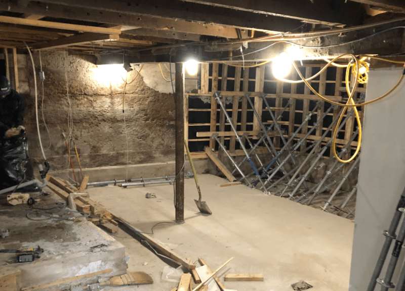
We're replacing some columns in the basement of an old building. When the columns are removed, I need to shore up an old 8"x8" wood beam. I can't simply place post shores beneath the wood beam since there needs to be clearance around the columns to pour new footings. So for this reason, I am using two props, which support an aluminum beam that runs perpendicular to the existing wood beam. I'm calling for beam clamps which will be used to connect the bottom flange of the aluminum beam to the top of the post shore. See Image below
Beam_Clamps_ozthbc.png

The GC is arguing these clamps aren't necessary because the beam and prop are secured together by friction. This falsework is enclosed in a basement (only about 8ft high ceiling) with no lateral loads imposed.
Wood_beam_h0wrum.png

I can understand that argument. My intuition says the beam clamps are necessary to restrain the ends of the beam from rotation. I don't want to cause extra work if it isn't necessary. I would appreciate to hear other thoughts on this.
Thanks
 
Replies continue below

Recommended for you

Someone not necessarily familiar with what goes on may come along and say place some material and bump the posts. Could be some mechanical equipment bumps the post, such as a concrete bucket thing or other.. It's better to be safe than sorry. That cramped location is prime target for an unexpected thing.
 
This probably falls into the 'means-and-methods' category, so the GC's responsibility.

The only time I relent on possibly NOT installing clamps/clips for shoring is when you use a cross-braced 4-leg tower shore/frame.

For you case, you basically have two isolated post-shores/props and a positive attachment from alum beam to shores is necessary, in my opinion.

Also, depending on how heavily loaded the alum beam is (and its depth) it has a tendency to 'roll' about its longitudinal axis. I often use wedged wood blocking each side of the alum beam web over the post-shores, after I install the clamps.

Besides, the T-slot bolts and clamps take all of 5 minutes to install.

 
Deener:
You do have to account for friction when it works against your design, but it is a very unreliable reaction force when it might act in your favor. Don’t rely on it in your design, it is just something of an added safety factor, you always have some problem pining down its value anyway, and sometimes that value may be very low. Use the clamps. Those clamps and the post cap pl. do not provide much lateral resistance at the top of the posts, so you must be sure to account for lateral stability in your design. The connections at the post cap pl./beam, and then btwn. the temp. (alum. bm.) and old beams are essentially pinned, and very unstable joints, they can roll over. You should brace these.

Is the old wooden bm. continuous over the old post? Maybe another way of framing your shoring would be with the shoring bm. (or bms., one each side) under and parallel to the old wooden bm. The shoring bms., about 10’ long, would canti. to with about 1’ of the old post, and the first shoring post would be back 3’ or 4’ from the old post, with a second post back 11’ from the old post.
 
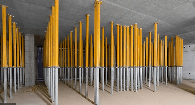
Thanks for all the helpful responses. I agree that it is good practice to not depend on friction in this case as it is difficult to quantify. The wood beam is not continuous over the existing columns. I have to stay close to those columns to minimize the length cantilevered off the shoring. Especially since there is collinear columns on the floor above causing a concentrated load on the beam. I like the idea of using the 4 leg cross braced tower. I'll keep that in mind. I believe lateral stability should be provided to the shoring in all cases. I think confusion is created when the GC is used to seeing pictures like the one below. Peri props used for reshoring without any apparent lateral bracing. They don't appear to be connected to the slab above. Does anyone know why this configuration works?
Props_lnm7dt.png
 
For reshoring, I don't see big problem for the props not to have bracing, since the load is more certain, unless there is a block party above. It was a common practice back to where I came.
 
I agree with Ingenuity on it being a means and methods issue. I would specify the clips even with push-back from the GC.

I'd like to tell myself that the application in your second image is a back shore application, not a reshore application; which makes me feel a little better about wedging the posts in there. Is it correct by engineering standards? Not necessarily, but in reality, it comes down to means and methods and for a back-shore application I think you'd find that they are wedged in there pretty well.

PS - The wall forms in the back of your first image are painful to look at...

Judgement-In-Training
 
Thanks for the input. @ Ceinostuv - since backshoring is still preventing the slab from deflecting under it's own weight, you're thinking the shores are wedged in place due to the self weight and therefore don't practically require lateral bracing? In contrast, reshores would be installed after the slab had deflected and thus would not be wedged in place with high forces. As for the wall forms, GC designed those themselves. Thought the width of the form mattered and the height didn't. The lesson was learned after the first blowout.
 
Deener, my thoughts exactly.

On those wall forms - I'd rather have someone overdo it than underdo it, I guess. Looks like they won't be having another blow out any time soon haha.

Best of luck with the project.

Judgement-In-Training
 
In the reshoring shown above, it is entirely possible a piece of spring steel is in place on top of the props.

But even without such, the prop would need to rack some amount to fall free. The wide baseplate of the props help this more than you might see with a wood shore.. We often install a piece of wood to tighten the prop into to give a bit of restraint on steel/aluminum props. But there are spring clips for this (spring clips are all but standard with wood reshores).


In the case of the props snugged to the aluminum beam, that is much more like a shoring use than a reshoring use (in terms of concrete construction usage) - if it were active shoring, a positive connection would be required to retain the shores. Instead of the beam clamp shown, I'd think an "A" clip or "J" clamp in the t-slot in the bottom of the aluminum beam (as suggested above) would be very easy and take seconds to install. As you are the shoring engineer, this stability is part of your design, and it is the needed means and method.

Daniel
 
Status
Not open for further replies.

Part and Inventory Search

Sponsor