Continue to Site

Eng-Tips is the largest engineering community on the Internet

Intelligent Work Forums for Engineering Professionals

  • Congratulations IDS on being selected by the Eng-Tips community for having the most helpful posts in the forums last week. Way to Go!

Short Circuit Current at Light Post Help 2

Status
Not open for further replies.

Mbrooke

Electrical
Nov 12, 2012
2,546
I'm getting only 62 amps short circuit current on my furthest light pole. Did I do my math righ? This number sounds awfully low.


For the POCO: 75 kva 3 phase transformer, 1% Z, 23,132 amps 3 phase fault.

Using ohms law I get a transformer value of: 0.00519 ohms


For the service:

Plastic PVC conduit, 600MCM copper- (0.039x0.039)+(0.023x0.023)=0.00205 root= 0.0452769256906871 /1000 x 25 feet = 0.0011319231422672 ohm

400MCM copper- (0.040x0.040) + (0.033x0.033)= 0.002689 root = 0.0518555686498567‬ /1000 x 25 feet= 0.0012963892162464‬ ohm

For the feeder:

# 3 copper in steal conduit- (0.059x0.059)+(0.25x0.25)= 0.065981 root= 0.2568676702117259 /1000 x 100 = 0.0256867670211726‬ ohm

# 8 copper EGC- (0.065x0.065)+(0.78x0.78)= 0.612625‬ root = 0.7827036476214992 ‬ /1000 x100= 0.0782703647621499 ohm

The branch circuit:

#12 copper THHN/THWN, PVC conduit-

live- (0.054x0.054)+(2.0x2.0)= 4.002916 root= 2.000728867188156‬ /1000 x 450 = 0.90032799023467ohm

ground- 0.90032799023467 ohm

Grand total= 1.912231424058514‬ ohms


Using ohms law at 120 volts I get 62.75396 amps.

Here is a single line:

 
Replies continue below

Recommended for you

Last question first.
It is possible for the neutral to carry more current than either of the line currents with widely different phase angles.
As for an easy way to calculate fault currents:
Digression warning:
Many years ago, an easy way was developed for both engineers and electricians.
It was found that switchgear would sometimes be destroyed trying to clear a fault.
Some way to correlate switchgear clearing capacity with grid capacity was needed.
The maximum current that a transformer will develop into a short circuit approaches an offset peak to peak current.
This depends on the transformer resistance, the transformer inductive reactance and on the point on wave that the short circuit occurs.
We are looking for the maximum so we will assume that the point on wave is the least desirable and exclude point on wave from the discussion.
That leaves the resistance and the inductive reactance.
Again, worst case the transformer saturates and the inductive reactance drops and the first cycle peak current approaches 2 x √2 = 2.83 times the RMS current.
How do we find an easy way for engineers, technicians and electricians to match switchgear clearing ratings with transformers offset currents.
The answer is the Available Short Circuit Current. (ASCC)
This is easily determined by dividing the transformer rated current by the %Impedance of the transformer.
The interrupting ratings of breakers and switchgear are ASCC values.
This needs only simple math.
Divide the transformer rated current by the %Imp and compare with the interupting rating printed on the circuit breaker.
What about the offset current?
When a breaker with a 10,000 Amps interrupting rating is tested, it is tested at the current that would result from an offset current at a typical transformer X:R ratio.
If you are working with low impedance transformers, it may be well to google interrupting ratings, testing and ASCC.
When a transformer X:R rating is above the test X:R, it may need higher rated switchgear.
I don't remember the specific X:R ratio.If I have to spec a low %Imp transformer I will refresh my memory.
So, the easy way is to use simple arithmetic and leave the hard math to the testers.
A suggestion:
Under short circuit conditions most of the resistance will be in the branch circuit.
Assume rated voltage applied to the branch circuit.
Breakers typically trip instantaneously at 10 times their rating, using a figure of 15 times (or your choice) will allow a safety margin and allow for some voltage drop in the feeders.
For each size breaker, list the maximum circuit impedance based on 120 Volts.
eg: 20 Amp breaker, use a minimum of 300 Amps.
120V / 300A = 0.4 Ohms maximum circuit resistance for a 20 Amp breaker at 120 Volts.
For 240 Volts, circuit resistance may be doubled.
You then may use two tables:
1. Maximum Ohms circuit resistance for a given breaker rating.
2. Ohms per 100 feet of the wire sizes under consideration.
This will allow the electricians to determine when a larger wire size is needed and to select the appropriate size.

Bill
--------------------
"Why not the best?"
Jimmy Carter
 
Warross said:
How do we find an easy way for engineers, technicians and electricians to match switchgear clearing ratings with transformers offset currents.
The answer is the Available Short Circuit Current. (ASCC)
This is easily determined by dividing the transformer rated current by the %Impedance of the transformer.
The interrupting ratings of breakers and switchgear are ASCC values.
This needs only simple math.

Two things I'm thinking about:

1) I've heard of single phase to neutral short circuit values at or very near the transformer exceeding L-L-L short circuit values by as much as 125%.

Is there any truth to this? How or why does it happen?

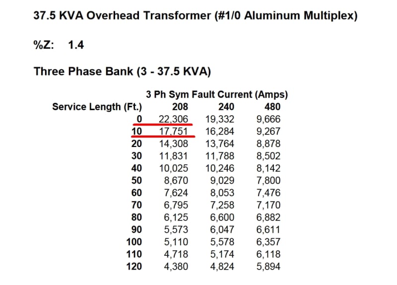
2) I'd like to include the conductors between the transformer and main disconnect when determining the AIC value of service equipment for NEC 110.9 and 110.24... For example, based on transformer impedance alone I'm over 22kaic, however if I include 10 feet of service drop I dip below 22,000 amps:

fault_current_0_feet_vs_10_feet_yepntq.jpg


22kaic vs 65kaic is money saved, legally allowed by the code. (Think of it like taking advantage of motor wire sizing rules, where I can save copper, material and labor by using 430.25 and 440.35 to its advantage)


Divide the transformer rated current by the %Imp and compare with the interupting rating printed on the circuit breaker.
What about the offset current?
When a breaker with a 10,000 Amps interrupting rating is tested, it is tested at the current that would result from an offset current at a typical transformer X:R ratio.

Correct if I'm wrong, but is it something like an X/R of 20? Or am I wrong thinking of something else?

If you are working with low impedance transformers, it may be well to google interrupting ratings, testing and ASCC.
When a transformer X:R rating is above the test X:R, it may need higher rated switchgear.
I don't remember the specific X:R ratio.If I have to spec a low %Imp transformer I will refresh my memory.
So, the easy way is to use simple arithmetic and leave the hard math to the testers.

I understand, but what about an electrician at the supply house doing a commercial service change? Going by own preconceived notions (which as a disclaimer could be very wrong), molded case breakers assume an X/R so serve it is not likely to ever be encountered in the real world.

A suggestion:
Under short circuit conditions most of the resistance will be in the branch circuit.
Assume rated voltage applied to the branch circuit.

Understood, but I'd like to include the whole picture including the service transformer, drop, and feeder. This IMO gives the best results, even if the actual value is off by 10%.

If I'm right, table 9 assumes a 75*C conductor temp for R, so, in theory, the final number will always be lower than the actual value. Which is good for disconnection times.

As is it was UL determined that a short circuit value 125% and over of a breaker's magnetic trip threshold reduced the incident energy at a short circuit to the degree that it meets the requirements of parallel arc fault protection.

Breakers typically trip instantaneously at 10 times their rating, using a figure of 15 times (or your choice) will allow a safety margin and allow for some voltage drop in the feeders.

I'm confused. Is voltage drop really important during a fault condition?

I mean yes the circuit becomes a voltage divider, where about 1/2 the normal line voltage is seen on the faulted object relative to remote earth.

It is for this reason why I am concerned about disconnection times, as values and duration exceeding the IEC's body graph can do harm to the human body.


Wiki said:
Log-log graph of the effect of alternating current I of duration T passing from left hand to feet as defined in IEC publication 60479-1.[21]
AC-1: imperceptible
AC-2: perceptible but no muscle reaction
AC-3: muscle contraction with reversible effects
AC-4: possible irreversible effects
AC-4.1: up to 5% probability of ventricular fibrillation
AC-4.2: 5-50% probability of fibrillation
AC-4.3: over 50% probability of fibrillation


For each size breaker, list the maximum circuit impedance based on 120 Volts.
eg: 20 Amp breaker, use a minimum of 300 Amps.
120V / 300A = 0.4 Ohms maximum circuit resistance for a 20 Amp breaker at 120 Volts.

Very doable! Good idea, thank you!

FWIW, this is why I want to reduce the POCO trafo to an R value.


For 240 Volts, circuit resistance may be doubled.
You then may use two tables:
1. Maximum Ohms circuit resistance for a given breaker rating.
2. Ohms per 100 feet of the wire sizes under consideration.
This will allow the electricians to determine when a larger wire size is needed and to select the appropriate size.

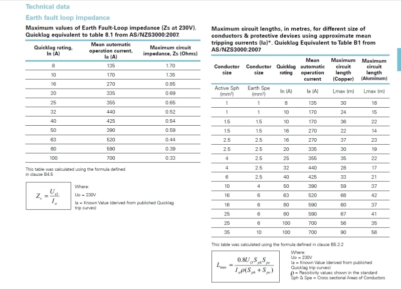
For number two- I want to take the whole system into consideration. At least that is how its done in BS7671...

Consider a ball field lighting application behind a school or college. There may be a 60, 125, 225 or 400 amp feeder going for some distance to a food service hut before the final branch circuit leaves that. Or a farm house to a work shop going beyond. Or a 60 amp life safety feeder going up 10 stories to a pent house panel in a plus sized building... yes I've seen prints asking for #6 on that one... no-no in my book.

Total Z I think is key.

Zs=Ze+(R1+R2)
 
And my apologies for being haughty if I'm coming off that way. Not my intent- most of this stuff is actually new to me and complex to be honest. I just recently realized that running several hundred feet of #12 out to a shed will not trip a breaker. Hence my moment of "awakening" if you will.
 
It's nice when one solution solves two problems.
It seldom happens in real life.
As I understand, you want or have a table to show minimum cable lengths to drop the ASCC to match the switchgear capability.
You also want a table showing the maximum cable length to unsure reliable tripping of branch circuit breakers.
In the one case you want to show a minimum cable length for currents in the order of tens of thousands of Amps on the main service conductors.
In the other case you want to show the maximum cable length for currents in the order of a few hundreds of Amps on the branch circuit conductors.
I would handle this as two distinct and separate issues.
You may combine the recommendations in one table.
I would use two tables.
Bill
--------------------
"Why not the best?"
Jimmy Carter
 
Waross said:
It's nice when one solution solves two problems.
It seldom happens in real life.
As I understand, you want or have a table to show minimum cable lengths to drop the ASCC to match the switchgear capability.

Yes- that is my goal.

You also want a table showing the maximum cable length to unsure reliable tripping of branch circuit breakers.
In the one case you want to show a minimum cable length for currents in the order of tens of thousands of Amps on the main service conductors.
In the other case you want to show the maximum cable length for currents in the order of a few hundreds of Amps on the branch circuit conductors.
I would handle this as two distinct and separate issues.
You may combine the recommendations in one table.
I would use two tables.
Bill

Yes- and I will take your recommendation. Much appreciated :)

Ok, two curve balls:

1) Parallel conductors

2) 480 to 120/208 transformers.

How do I calc these two?

BTW tell me if this is correct:

Instead of adding the R and X of each condcutor, you first add all the Rs then all the Xs, then use the equation RxR+XxX=root of the number.

Or is my way more accurate?
 
√((R+R+R...)2+(X+X+X...)2) Will give you the impedance of the complete circuit.
From that you may calculate the current.
The current may then be used to calculate the voltage drop of each section of the circuit.
Remember that the sum of the voltage drops will be greater than the total actual voltage drop.

Bill
--------------------
"Why not the best?"
Jimmy Carter
 
Ok. Question- I mean it will become obvious when I crunch the numbers- but how does this method differ from adding RxR and XxX for each section and then summing them all together? Just curious.

I'm still trying to pin point a good R and X for the trafo..
 
Consider an ideal circuit, pure resistance (3 units Ohms) in one section, pure inductance (4 units j units Ohms) in the other section.
Apply 100 Volts AC.
You will see 60 Volts across the resistor and 80 Volts across the inductor.
60 Volts plus 80 Volts does not equal the 100 volts applied.
Phase angle only matters if you want the right answer.
Please review vectors and directed numbers.


Bill
--------------------
"Why not the best?"
Jimmy Carter
 
Yes- but remember vectors would become a mess if electricians had to do them on site.
 
Status
Not open for further replies.

Part and Inventory Search

Sponsor