Hello,
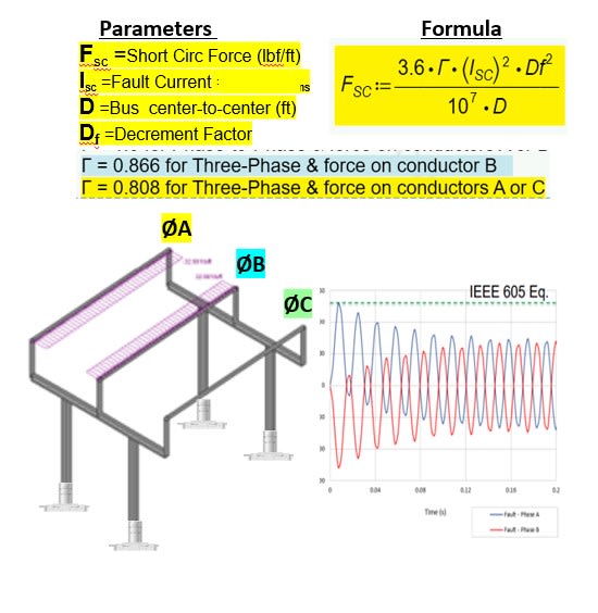
I am wondering how to compute the short circuit force that would be exerted on (3) aluminum bus bars within a 3 phase transformer. Here are the specs:
2750 kVA 3 phase transformer
HV voltage is 13200Y/7620
LV voltage is 600 Delta
LV current is 1528A
(3) LV bushings on right side of transformer
# of bus bars = 3
Bus bar dimensions are : 42.5" long x 6.00" wide x 0.5" thk
I would use Inventor to simulate the force of stabilizing stiffeners to see if I need to see if a change to the stiffener shape is needed.