Continue to Site

Eng-Tips is the largest engineering community on the Internet

Intelligent Work Forums for Engineering Professionals

  • Congratulations IDS on being selected by the Eng-Tips community for having the most helpful posts in the forums last week. Way to Go!

Short Circuit Force on Aluminum Bus Bars

Status
Not open for further replies.

kevc70

Mechanical
Jul 15, 2009
37
Hello,

I am wondering how to compute the short circuit force that would be exerted on (3) aluminum bus bars within a 3 phase transformer. Here are the specs:

2750 kVA 3 phase transformer
HV voltage is 13200Y/7620
LV voltage is 600 Delta
LV current is 1528A
(3) LV bushings on right side of transformer
# of bus bars = 3
Bus bar dimensions are : 42.5" long x 6.00" wide x 0.5" thk

I would use Inventor to simulate the force of stabilizing stiffeners to see if I need to see if a change to the stiffener shape is needed.
 
Replies continue below

Recommended for you

Electromagnetic or from thermal expansion?
 
For this study it would be electromagnetic.
 
Mr. kevc70 (Mechanical)(OP)16 Aug 23 05:35
"....I am wondering how to compute the short circuit force that would be exerted on (3) aluminum bus bars within a 3 phase transformer....Bus bar dimensions are : 42.5" long x 6.00" wide x 0.5" thk..."
1. The basic data needed to calculate the maximum force appearing on any phase resulting from a fully offset asymmetrical peak current:
a) is proportional to the current square ( I2), and
b)is inversely proportional to the spacing distances of the centre-line between phases. Note: Please clarify 3bars per phase or 1bar per phase.
2. For a) we can calculate the [short-circuit current] if you can furnish the percentage impedance (%Z), taken from the transformer name-plate.
For b) you have to take the measurement from the drawing or better from the actual site measurement.
3. We may be able to make some computation with abovementioned data.
Che Kuan Yau (Singapore)
 
Hello,

1. The %Z from the transformer nameplate is 5.85. There is (1) bus bar per phase.

2. The spacing between the each of the bus bars is 6.25" center to center.
 
Mr. kevc70 (Mechanical)(OP)16 Aug 23 05:35
There are numerous valuable advice by learned readers.
I am suggesting the following for your consideration. Please verify whether it make sense. Thank you.
My understanding the maximum on the center phase is
F = [8.66 x 2 x [I']2x 10⁻⁴]/s in (N/m).
= 8.66 x (68.22)/158 = 3.717 in (N/m)
Note: 1. the offset factor n is taken as 2.55,
2. Irms is taken 1528A/0.058 = 26,119.6 in (Arms),
3. s in mm 6.25 in = 158.75 mm,
4. the force[/b is independent of whether the bar is of copper or aluminum.
Che Kuan Yau (Singapore)
 
For force calculations I strongly recommend a temperature correction.
Peak short circuit current is closely related to the resistance of the windings.
Percent impedance tests are done with the transformer at rated temperature.
At room temperature the resistance is lower and the current is higher. Then the current is squared.
Doing a percent impedance test at room temperature, the effect is noticeable. (Don't ask how I know. It was not expensive but it was embarrassing.)

--------------------
Ohm's law
Not just a good idea;
It's the LAW!
 
@ Mr. waross (Electrical)17 Aug 23 10:50
"...For force calculations I strongly recommend a temperature correction. Peak short circuit current is closely related to the resistance of the windings. Percent impedance tests are done with the transformer at rated temperature. At room temperature the resistance is lower and the current is higher".
1. It is common sense that the peak short circuit current is closely related to the X and R , not R alone. Noted that R increases with temperature while X is not.
2. While the exact value of X and R are unknown, I suggested the pf = 0.07 which corresponds to n factor of 2.55 ; in my earlier post.
Please advise whether the factor of 2.55 is in order. Your advice are welcome.
Che Kuan Yau (Singapore)
 
If transformer L.V. short-circuit it is ukr= 5.85%, the impedance will be:
ZT=ukr%/100*Urt^2/SrT where Urt=0.6 kV and SrT=2.75 MVA.
ZT=5.85/100*0.6^2/2.75=0.007658182 ohm
If the supply system impedance=0 then
Ik”=600/sqrt(3)/ 0.007658182/sqrt(3) =26115.86 A[rms] three-phase short-circuit.
Line-to-line short circuit
Ip2=sqrt(3)/2*Ik”= 22617 A[rms]
Ipeak=k*sqrt(2)*Ip2
Since we don’t know what is X/R of the transformer impedance we take the maximum k=2
Ipeak2=2*sqrt(2)*22617=63970.54 A
According to Schneider brochure no. 162 electrodynamic forces on busbars in LV systems:
F/lng = 2* 10-7* I1* I2 (k/d)
lng=42.5”= 1.0795 m
d=0.15875 m
If d/a=12.5 and b/a=12 k=0.87 [see the attached image]
k=0.87 vertical bars
F2=1.0795*2/10^7*63970.54^2*0.87/0.15875=4841.927 N
If we consider three-phase short-circuit then
Ipeak3=2*sqrt(2)*26115.86=73866.8 A and then
F3=1.0795*2/10^7*73866.8^2*0.87/0.15875=6455.9 N
 
 https://files.engineering.com/getfile.aspx?folder=206b2485-eafc-4693-96f4-0c570b8b07c5&file=Schneider_162_k_for_short-circuit.jpg
7anoter4; I didn't see a temperature correction.
Did I miss something?
Nameplate percent impedance is measured with the transformer at operating temperature.
Short circuit current will be greater in a cold transformer, as for instance, a fault during commissioning.
The impedance of the cold transformer must either be measured or corrected from the nameplate value.
Try sending a group of students to the shop to verify the nameplate percent impedance of some transformers.
They will not be able to match the test values of impedance with the nameplate values of impedance unless they correct for temperature.


--------------------
Ohm's law
Not just a good idea;
It's the LAW!
 
You are right, waross. There are some factors as voltage tolerance and temperature rise not considered. The IEC 60909-0 standard takes into consideration voltage tolerance introducing factor c [for maximum and minimum supply voltage], but I don't know standard required temperature correction.
For electrodynamic forces the maximum force is important, that means
at no-load state is better.
However, if X/R=10 the difference between 90oC -full load-and 40oC
for no-load it is negligible.
Let’s ZT= 0.007658182 ohm and X/R=10 [see ANSI Standard C37.010]
XT=ZT/SQRT(1+1/100)= 0.007620176 ohm and RT90oC=XT/10= 0.000762018 ohm.
kT=(234.5+90)/(234.5+40)= 1.182149
RT40oC=RT90oC/kT =0.000762018/1.182149=0.000645 ohm
ZT40oC=sqrt(0.007620176^2+0.000645^2)= 0.007647 ohm
0.007658182/0.007647=1.001462 [1.46 per 1000]
 
In Canadian winters work often continues at -20C and -30C.
When a billion dollar project is coming online and interest charges per day are in the millions of dollars, test and commisioning does not slow down for the weather.
Switch-rooms may be heated but large transformers may not be heated.


--------------------
Ohm's law
Not just a good idea;
It's the LAW!
 
If Ta=-40oC then kT=(234.5+90)/(234.5-40)=1.6684
RT(-40)=0.000762018/1.668=0.000457
ZT(-40)=sqrt(0.007620^2+0.000457^2)=0.007634
ZT(90oC)/ZT(-40oc)=0.007658/0.007634=1.003144 [0.3144% less]
However, according to ANSI C37.010, even for 750 kVA where X/R=5
[and ukr%=6 ]
ZT90oC=6/100*0.6^2/0.750=0.0288 ohm
XT=0.0288/sqrt(1+1/25)=0.028241
RT(90)=0.028241/5=0.005648
RT(-40)=0.005648/1.6684=0.003385
ZT(-40)=sqrt(0.028241^2+0.003385^2)=0.028443
ZT(90)/ZT(-40)=0.0288/0.028443=1.012551 [1.2% less]
 
Thank you for the responses so far!

Here is some additional information for this transformer:

The insulating fluid is FR3.
The X/R ratio is 6.7
Total Secondary resistance is 0.12810E-02 @85C, and .10331E-02 @ 25C.
Step up transformer
65 degree average winding rise
KNAN cooling class

Where does the short circuit force physically act on the bus bars? The bus bars are each supported inside the transformer by (4)GPO-3 stiffener pieces that anchor the assembly to the LV bushings mounted near the bottom of the transformer. Is the force computed above (6455.9 N) acting on all (3) bus bars at once? Would it be possible to attach the force equation from the Schneider brochure?


Thanks to your new data and for the remark that my response was" so far" I remember I had no time to revise the calculation.
I found that calculating Ik" I divided twice by sqrt(3)
[see my post of 24 Aug 23 08:39]
Ik”=600/sqrt(3)/ 0.007658182/sqrt(3) =26115.86 A
Actually Ik"=600/sqrt(3)/ 0.007658182=45234 A
Revising the force calculation, introducing the last data and the waross remarks the result is 13276.3 N. [it is not 6455.9 N, I apologize].
No problem to attach some instructions from Schneider brochure.
However, I don't think you can finish the transformer design check based on our posts. The forum scope it is only as Engineer Tips only.
I was involved once in transformer design and I know the workshop practice is more detailed.
Some details are neglected, for instance-generator or system- impedance. Also, the voltage tolerance [what is the maximum supplied].

 
kevc70 said:
"Is the force computed above (6455.9 N) acting on all (3) bus bars at once? "
Of course not. I forgot to multiply by 0.866-as che12345 did.
I have not time to read all the posts-I am sorry-and it is not good.

 
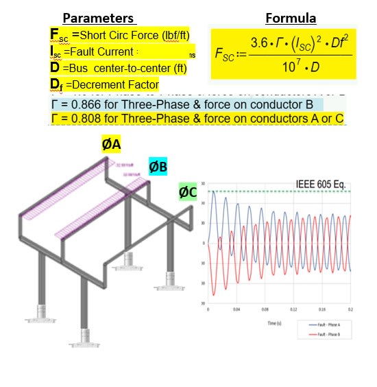
SC_Forces_on_Rigid_Bus_run7wx.jpg
 
Status
Not open for further replies.

Part and Inventory Search

Sponsor