Eng-Tips is the largest engineering community on the Internet

Intelligent Work Forums for Engineering Professionals

Short Slots in Collectors 1

Status
Not open for further replies.

SteelPE

Structural
Mar 9, 2006
2,737
0
36
US
I am currently in the process of reviewing shop drawings for a very large warehouse type structure. The structure was designed in accordance with IBC 2015/AISC 14th edition. I located the LFRS (lateral force resisting system) around the perimeter of the building utilizing a concentric brace frame.

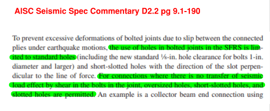
At the perimeter steel, the fabrication is calling for short slots in all of the beam to column connections. I would like to avoid this type of hole in these elements as these beams are acting as collectors for the brace frame system. Out of interest, I went digging into the AISC and they seem to allow for short slotted holes at the discretion of the EOR. The commentary has some discussion about why short slots are allows.... and shocker, it has to do with allowing for proper plumbing of the columns.

In this instance, where the perimeter beams are acting as a collector for the LFRS what are others doing? Are you allowing for short slots to be used in this instance? or do you insist on STD holes?
 
Replies continue below

Recommended for you

I'm not sure about your seismic requirements, but the AISC Seismic Specs do have some requirements. Otherwise, I don't know of any limitations on the topic.

For what it's worth, I use SSL holes w/ slip critical bolts quite frequently for collectors adjacent to braced frames, but I don't do work in high seismic regions.

AIsc_up15wn.png
 
If you have bunch of these, field welding would be cost prohibitive.

I'd have to look it up, but don't short slots add very little travel in the direction of the slot? Like an extra 1/8"? This seems pretty small if you consider the way things move around in a major seismic event. The short slots may even serve to dissipate some energy and be better performers than 1/16" oversized holes.

Most of the time fabricators want to "torque" everything down, so under less-than-ultimate level forces you probably don't get any slippage in the joint at all.
 
To be clear, the connections are bearing type connections and not slip critical.

I understand the comments. The bolts are typically 3/4" making the short slots 13/16"x1"... so yes, if the bolts were centered perfectly you are looking at 1/8" per bolts (or 1/4" at every column). There are approximately 10-12 column per collector run... so we would be looking at a movement of approximately 3" over a length of 200' ish.

As of now, we are telling the fabricator to use 13/16" dia holes (standard holes) but I expect to get pushback sometime soon.
 
I've used standard holes on these and have gotten only a little pushback.

Another option is to ask the EOR to approve. My guess is he or she would look at J3 and not approve slots. I probably wouldn't hold up the schedule for the small chance of approval. Unless the fabricator was having a cow over standard holes, that is.

If I was an EOR, I would not approve slots with bearing connections in this case.

Edit: Here's another angle on this. If you ask for approval, the eor might come back with SC connections. Considering how hard it is to make those work, that might be a bad outcome.
 
XR250 said:
What is the issue of using slip-critical fasteners?

I would imagine the surface prep... Can't say that I have every really used SC bolts in my 20 year career. I would think with modern fabrication techniques that they would be able to fabricate the beams and columns properly... so it's really just a question on the placement of the bolts. I anticipate a few bolts to be misplaced, but I know the site super really well, and I don't see him going off and placing hundreds of bolts in the wrong location... and the bases tend to have enlarged holes.... so I would like to think they could make it work.
 
XR250 said:
What is the issue of using slip-critical fasteners?
In many cases, it's hard to get them to work for the loads.

Imagine a W10 beam with a required shear strength of 25 kips LRFD. There's only room for two bolt rows, but the slip resistance for 3/4 in. A325 is only 9.49 kips/bolt. You end up having four bolts in a 2x2 pattern to make it work. With bearing, two bolts would be fine.
 
I don't want to get into a SC vs bearing discussion in this thread. I have been around the block more than a few times and have W16's and W18's where a W12 would have done perfectly fine. This was all planned to make connections easier. At most, I have 19 kips of shear on these connections.
 
Years ago before all the fancy equipment to make slots efficiently, they could use standard holes, so I would think they still can. I would mark it up and move forward.

"do EOR's not review shop drawings anymore?.." Not so much in my role as a delegated designer. A giant stack of dwgs was sent for review and the only comment back was about a dowel being 1/16" out of alignment. I thought, thanks for coming out. Last year an old dog was reviewing drawings and I got a lot of practical questions. It was refreshing. I see in a lot of cases the review is left for junior engineers with the assumption their EOR dwgs show everything they should need to know.
 
Usually I allow the use of short slots in collectors personally. IMO, it depends on the building construction, but for warehouse style construction (steel superstructure, metal deck diaphragm, metal cladding, etc), these structures are quite flexible-- any movement from bolt slip will not cause issues with the building envelope. The only other issue would be the potential for 'bolt banging' which is a serviceability issue (not one I've ever actually heard of happening however) not a strength issue.

I do think AISC is a bit unclear on if this practice is 'technically' allowed, as chapter J does say that slots are not permitted in the direction of loading which for collector loads that would be a violation of, but if you can reason to yourself that it is not adversely affecting the structural performance of the building and can accept the potential for additional movement I think it is a good way to help allow the erector some flexibility. For reference, PEMB structures use H/60 drift limit for a 10 year wind. These things can move alot more than you may think.

For a building with tilt up walls for example, I may feel a little differently since I would usually want to limit drift more in those cases.

Also, could you meet in the middle and allow short slots on one end of each beam only rather than both? This would cut your potential accumulated slip in half.
 
SteelPE said:
I would think with modern fabrication techniques that they would be able to fabricate the beams and columns properly
I believe the issue is usually the mill tolerances on the W-sections. All of the parts and plates can be cut out perfectly, but when one (or all) of your wide flange columns is 1/4" deeper than it is "supposed to be" and the web is 3/16" off center, that needs to be accounted for somehow. Fabrication shops are going to try to avoid custom detailing all of the connecting parts based on the specific mill tolerance of each W-Section, the easiest way to do this is using short slots.
Mill_Tolerances_gujqps.png

 
Never had a problem with standard holes when they're required in situations like this. In fact, I have had erectors say they preferred them over short slotted - less slop when going to plumb/square things up.
 
SteelPE - I suppose the biggest question is this: can your columns in the middle of the building handle being 3"+maximum plumb tolerance+maximum diaphragm deflection out? If not, you'll need to limit that movement somehow.

Do you have an edge angle? That'll probably be welded anyway. Can you size splices so it can act as a collector? Might need to reduce the pitch/increase the length of the welds to the beam at the braced frame. Then the erector gets short slots (if they so desire them), and you get a continuous collector with no slop.
 
Good point about the edge angle... Yes, there is one, but it sits on top of open-web steel joists 1'-4" away from centerline of steel, so I don't think the angle is even remotely capable of acting as a collector when the joist seats will need to take the load from the angle to the supported beam below.

Before everyone gets their panties in a bunch.... we have specified shear collectors on top of the beams in some areas (that will be directly welded to the decking) and in areas w/o these shear collectors we have specified a rollover capacity for the joist seat.
 
Ah. I see. A big overhang/offset like that would impair it a bit. You'd have to do some interesting sub-diaphragm detailing to make it work.

Sounds like standard holes are the way to go, then, unless the frame and cladding can handle the movement.

 
Yes, we have an overhang. The building is clad in insulated metal panel with outset 8" girts. We are using 14" columns and the architect wanted an extra 1" in there for good measure.... so 1'-4" to edge of foundation/angle.

We are going to specify STD holes for now and wait until the fabricator complains. They have complained about a lot of things already and we haven't even submitted our review for Zone 1 yet. Should be interesting.
 
Status
Not open for further replies.
Back
Top