Eng-Tips is the largest engineering community on the Internet

Intelligent Work Forums for Engineering Professionals

Should I recognize the beam connected to a general wall as a collector? 3

Status
Not open for further replies.

Rosebay

Structural
Dec 16, 2021
10
0
0
US
Please see the picture. Assume this is one story wood structure building under seismic control. The shearwalls are at exterior walls both side (the red lines)

7A9143B2-AD2D-470A-A664-AA7C0EA7479D_u6kwtd.jpg


My question is May I treat the beam at line B as a collector (the green line) if there is no interior & exterior shearwalls on line B?

Thanks
 
Replies continue below

Recommended for you

1) The sketch below would have been my version of TLHS's model. I don't dispute that there are other viable stories that can be told to satisfy equilibrium. However:

a) The other stories often complicate the connection detailing of the deck and/or infill framing and;

b) The model shown below is what I see done 99% of the time in practice and in the literature.

2) As far as a definition of what constitutes a "collector" in the context of diaphragm design, I feel that it should be this:

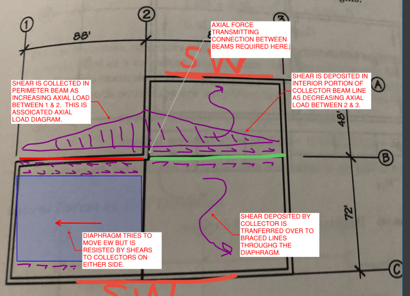
A collector is any member that participates significantly in transmitting local diaphragm shear stresses from their points of origin to the vertical lateral force resisting systems whereby the shears exit the diaphragm.

By this definition, the green beam is a "collector" even though it's job is, technically, to deposit / distribute shear stresses rather than collect / aggregate them.

3) In many respects, I feel that it would be an improvement to define Collector Framing Lines rather than collector members. Collector members would then then just be the components of collector framing lines that may either be in the business of collecting shear or depositing it as required by the situation.

4) In a very real way, framing line B can be envisioned as part of both framing lines A & C when it comes to the collector definition. That, because the shears collected on framing line B ultimately get transmitted over to lines A & C via the diaphragm between lines 2 & 3. The situation is much like that of an offset rebar splice in concrete design.

c01_eylprx.png
 
Yeah, what Koot's sketched there is what I was considering. I never really clarified that the beam along B has to extend into the region between 1 and 2.

JLNJ: I'd agree that there are clearly some scenarios (aspect ratios and sizes) where you could transfer the load internal to the diaphragm through a shear field action or some sort or tension/compression in the decking. However, conversely, there are times when that also clearly isn't the case and the capacity of the diaphragm would be overwhelmed by those additional factors. Evaluating that consistently and detailing to suit seems tricky. I'm open to seeing it, though

 
JLNJ,
The common way to think of diaphragms is acting only in shear, with separate members wherever tension/compression is needed. In this model, line B must collect and deposit seismic load per TLHS diagram. If the diaphragm can resist axial loads, you wouldn't technically even need a collector in line with every LFRS.

Or, perhaps you have LFRS on lines 1 and 2, so the blue section is it's own separate 3 sided structure. But you probably don't want a gap opening up along line B, so you'd connect with a collector anyway.

 
I`m with JLNJ on this one.
I`d design and detail my diaphragm as a rectangle, bound by A/C, 2/3 and spanning from shear wall to shear wall.
If this rectangular diaphragm had twice as much dead load from B-C as from A-B, we wouldn't need any diaphragm/collector elements on grid B.
In our case, I assume we have a uniform dead load but twice as much area, and still don't need any diaphragm/collector elements on grid B.
(Please note that I`m only considering EW loads).

I seems to me like everyone advocating for a collector is ignoring the continuity of the deck.
If you refer to TLHS's Jan 3rd sketch, they`re showing a single point of force transfer at gridline B. It's as though the blue area is being considered as a simple span from B-C and creating a point load.
I expect that the force will be transferred in a continuous manner between B and C, therefore there is no point load at B to address.
The reference to ASCE 7-16 C12.10-1 is interesting, but C12.10-2 is even MORE interesting, it appears to show this exact situation without a collector at the re-entrant corner.

Note again that the diaphragm I`m describing does not work in the NS direction, but that's not the question at hand here.
 
"I expect that the force will be transferred in a continuous manner between B and C, therefore there is no point load at B to address."

Are the nails in the panels or joist hangers between B and C designed for this?

Would your answer change is this was a steel deck with ribs running N-S?
 
271828 - maybe we're coming at this from different points of view, I`m accustomed to steel deck & steel joists.
For steel, the shear at gridline C would be higher than A, and the diaphragm attachment would consider that higher shear.
The capacity of a steel deck diaphragm is independent of the direction of the ribs, and that would not impact my opinion.

There's no information in the question posed about the direction of the floor framing, so I think joist hangers are irrelevant.
 
Status
Not open for further replies.
Back
Top