Eng-Tips is the largest engineering community on the Internet

Intelligent Work Forums for Engineering Professionals

Should primary datum be top or bottom and projected tolerance zone

Status
Not open for further replies.

sendithard

Industrial
Aug 26, 2021
166
0
0
US
As I was a newbie learning gd&t the selection of the primary datum always seemed strange to me and I'm surprised it took me this long to ask this question.

If you drill from the top down thru a square part is it proper to keep the top surface as datum A or should you use the bottom for Datum A? I was taught manual inspection prior to learning GDT so my baseline goto is throw her down on the surface plate and that is your datum A...but that would be where the hole extrudes out of and not the entry location. Then I start thinking about the datum A of the threaded hole joining part only going halfway thru the part, so Datum A on top where the hole is tapped would be preferred, but can you somehow us the bottom of a blind hole part as datum A? I'm all confused on if there is proper use of the bottom and top surface as datum A.

This all hit me when learning projected tolerance zone. B/C do you project from said datum or is it perhaps implied the projection extends where parts meet, etc.

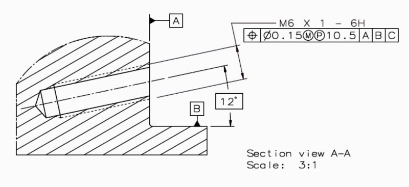
Attached is the pic that set my mind wondering dealing with projection tol zone. For instance, in the bottom pic I don't think it makes sense to use the bottom surface as datum A b/c it is a blind hole....but I have seen thru holes use both surfaces. So it makes me wonder could you use the bottom surface in the bottom pic as Datum A. And if so is that perhaps bad form. And then where would the projected tolerance start? Thanks as always.

projected_eaggrf.jpg
 
Replies continue below

Recommended for you

sendithard,

Think of your datums as a fixturing specification. Try to visualise your fabrication and inspection fixtures. Must of the time, your best primary datum feature is your part's mount face.

GD&T is a language, not a procedure.

--
JHG
 
You use the projected tolerance zone to solve issues related with orientation error of the screw, stud or dowel pin relative to the mating face between the parts, so for this application it is only logical to use the mating face as a primary datum feature for the positional tolerance of the holes, to minimize said error.  The Y14.5 standard doesn't cover any other scenario, so although the choice of datum features is up to you as the designer, you won't find anywhere a rigorous description of how the start location of the tolerance zone is decided when it is not projected from a datum plane.
 
sendithard,

Datum feature selection should be driven by how the part functions/assembles - not how it is manufactured/processed or inspected. Obviously in the real world we have to make concessions for the latter, however priority should always be given to function.

I know its a relatively fine line, and I'm not sure how clear the difference is going to be by my explanation - but datum feature selection doesn't affect the extent of the tolerance zone (ie: where it starts and ends), it only affects how that tolerance zone is constrained in translation/rotation wrt some reference. For most tolerances per ASME Y14.5-2018 para 4.1 FUNDAMENTAL RULES section (o) "UOS, all tolerances and datum features apply for full depth, length, and width of the feature" So for example a standard position tolerance for a hole applies for the full depth of the hole regardless of what datum features are specified - however depending on your datum features it might be located/oriented slightly differently. In this particular case we do have a tolerance which is considered "otherwise specified" as the tolerance zone extends beyond the feature, however still regardless of your datum features it starts at the surface of the hole and is projected 14mm above.
 
Burunduk,

While Y14.5 doesn't cover any other scenario, Y14.5.1 does have provisions for it. I think you'll agree that this isn't the only case that Y14.5 is lacking rigor. I'll preface the below by saying that it might be purely academic, my point is only in saying that the tools are there.

Per Y14.5.1 para 5.3 the projected tolerance zone is projected above a "contacting plane" - which admittedly could be defined better but is at least specified as a plane perpendicular to the true position axis which I don't think its a large leap to assume is required to be outside the material and making minimum one point of contact. In this respect I think the projected tolerance is actually better defined as to the extent of the tolerance zone - for a standard position tolerance in Y14.5.1-1994 para 5.2 it simply states "the feature axis extends for the full length of the feature" with no exact definition as to how to unambiguously determine this "full length", no different than what is found in Y14.5. There could be some differences in interpretation especially for example holes/countersinks in irregular/curved surfaces (or even nominally flat surfaces that are not nominally perpendicular to the true position axis). Speaking of irregular surfaces, the definition for a projected tolerance doesn't seem to hold up on anything other than a nominally flat surface which is also perpendicular to the true position axis - or at least it will generate an unexpected result, however that would be a dubious application to begin with.
 
chez311, kudos for directing to Y14.5.1, it does seem to provide some useful guidance on this. I agree with your interpretation, and it seems reasonable that the OP can conclude that even if any surface other than the mating face is selected as the primary datum feature for the projected position tolerance (although once again, I don't see a good case for it), the tolerance zone still starts at a theoretical plane contacting the face into which the hole enters and normal to the true position axis. I also think that the assumption you made that the said contacting plane should make at least one point of contact with the corresponding part surface is sensible.

 A couple of issues, though. First, unlike when the tolerance zone starts from a datum plane as shown in the Y14.5 examples, you can't have a fully defined tolerance zone prior to having the physical part on hand, since the "contacting plane" may vary relative to the datum reference frame according to the tolerances applied on the surface into which the hole enters. And since the starting point and extent of the tolerance zone is particularly important for conformance in the projected case, it could become a practical problem for preparation of inspection programs etc.
Secondly and more importantly, I don't think that the case of a planar surface not nominally normal to the hole per the design is "dubious".
See the image below. It shows a case where there's a corner  in the toleranced part towards which a component of the assembly should mount rigidly. It may be wanted to direct the screw in such a way that a component of the clamping force exerted by it acts towards datum feature B. In this case the specificstion that the "contacting plane" should be normal to the true position axis does no good. Instead, it would be better if the standard specified that the contacting plane should be either normal to the true position axis or oriented to it according to the appropriate basic angle that corresponds with the design.

20220213_094356_zo5c4z.jpg
 
Burunduk,

You make some good points. In the general cases I came up with in my head it didn't seem to be viable, but the more I think about it the less improbable they seem. While perhaps uncommon they are not unreasonable possibilities - it doesn't seem the committee took those into account, and the same "contacting plane" appears in the Y14.5.1 draft I have, assuming it went unchanged in the final version.
 
Since this thread is not too old and my question is related, I'm going to resurrect this.

I am designing a probe holder - pencil-type probe held in a small block. The block has a hole in it for a bushing, then the pencil probe goes in the bushing. We assign a positional tolerance on the hole in the block with a 4 inch projected tolerance to make sure the probe ends up where it should. The hole in the block is a thru hole, but we want to hold the projected tolerance only in one direction.

Bottom line question: how do we denote which direction the projected tolerance should go?

Thanks!

Thinking further on this, I'm thinking it doesn't matter. If it is within the projected tolerance zone in one direction, it will also be in that zone in the other direction. Is that true?

Thanks again!
 
randy64,
You could graphically show the projected tolerance zone at the side where it applies by use of a chain line. See the below image. A similar figure can be found in the 2009 edition of the standard in section 7.

Screenshot_20220713-062116_Office_glb5y0.jpg


And the projection side does matter. When the actual hole axis is produced with an orientation error it could pass the inspection when projected in one direction and fail if projected in the opposite direction.
 
Burunduk, can you show me graphically how it can be good in one direction, but off in the other? It seems to me that the hole has one centerline, one orientation that will project the same in either direction. What am I missing?

Thanks
 
Randy64 -- the hole has one center axis, yes, but if it the two faces of the part aren't perfectly parallel, then the orientation to one face will seem different than the orientation to the other face.

John-Paul Belanger
Certified Sr. GD&T Professional
Geometric Learning Systems
 
Belanger,

So you're saying that the orientation of the projected "soda straw" is based on the face? I thought it is based on the center axis of the hole, which makes the face immaterial.

In my example, the pencil probe will go where it's going to go (projection) based on the axis of the hole, not whatever is happening with the faces of the block.

EDIT:

I should think a little more before I post. I think I get it now. Projection IS based on the face - otherwise how would you know what direction to project from? It must be perpendicular to the face, and since the faces could be out of parallel, then it becomes important to denote which direction you want the projection to go.

Thanks!
 
No problem.
Just a bit more detail...The axis of the actual hole must fall within the "tolerance zone" which is perfectly oriented to the primary datum. If the primary datum is altered so that it comes from the other face, the tolerance zone will be perfectly oriented to that new datum, but that may make the hole's axis fail to comply with that new tolerance zone.

John-Paul Belanger
Certified Sr. GD&T Professional
Geometric Learning Systems
 
randy64 said:
Burunduk, can you show me graphically how it can be good in one direction, but off in the other? It seems to me that the hole has one centerline, one orientation that will project the same in either direction. What am I missing?

projected_tol._zone_umqvwt.jpg


The hole is conforming to the projected tol. zone when it is projected from the top, but not from the bottom.
Note how it has nothing to do with parallelism error between the top and bottom. In my model they are perfectly parallel.

randy64 said:
Projection IS based on the face - otherwise how would you know what direction to project from? It must be perpendicular to the face, and since the faces could be out of parallel, then it becomes important to denote which direction you want the projection to go.

This is not entirely true. As discussed above in this thread, the projection is normal to a "contacting plane" which is perpendicular to the true position axis, which is in turn basically oriented to the DRF. So essentially the projection direction is based on the DRF. That is true even if the face from which the tolerance is projected is not used as a datum feature.
 
Status
Not open for further replies.
Back
Top