Continue to Site

Eng-Tips is the largest engineering community on the Internet

Intelligent Work Forums for Engineering Professionals

  • Congratulations KootK on being selected by the Eng-Tips community for having the most helpful posts in the forums last week. Way to Go!

Should storm drainage systems be designed for uniform flow or gradually varied flow? 1

Status
Not open for further replies.

Akel

Civil/Environmental
May 22, 2012
33
Hello all,

HEC-22 assumes that water is flowing under uniform flow conditions and the pipes are sized so that the pipe capacity is always larger than the incoming flow. On the other hand, computer software (such as stormcad) calculates using gradually varied flow conditions, and the water surface profiles sometimes shows that pipes are not flowing full even if the incoming flow is 300% the pipe's capacity. This of course allows for a much more economical design since smaller pipe diameters can be used for larger flows.

Is it safe trust stormcad and size my pipes for gradually varied flow conditions, or do I just stick to HEC-22 assumptions and design for uniform flow?

Thank you.
 
Replies continue below

Recommended for you

if you don't trust stromcad check with Manning equation, it should give the same size, also please understand how stormcad calculates the discharge. i think you can go ahead with the size of the stormcad. please let me how you are calculating discharge, in stormcad or applying as known flow?
 
First, please do realize that the flows themselves are borked for either method. Let's take a step back.

StormCAD and other softwares typically use the modified rational method to develop their catchment flows. What does that mean? It means the flow in the first pipe is based on the Tc of the first catchment, lets say 5 minutes. So it's a rational Q=CIA flow with an I pulled off the IDF curve for a 5 minute storm. What about the 2nd pipe? Well, now things get tricky.

When StormCAD does the 2nd inlet, it uses the Tc you unput for the inlet catchment, perhaps also 5 minutes, to do its pavement hydraulics calculations (gutter spread). But then when it calculates the flow rate in the pipe, it throws out the two incoming flow rates and recalculates a new Q=CIA based on the longest travel time to the pipe. So that could be the Tc of the second catchment, or as is more often the case, the Tc of the first catchment plus the travel time in the pipe. So you could have the Tc of both catchments be 5 minutes, and the travel time down the pipe between inlet 1 and 2 is a minute, and the flow in pipe 2 would be based on Q=CIA, with the I pulled off the IDF curve for *six* minutes, not five. And the further you go down your network, the longer the Tc will be that StormCAD uses to calc the pipes.

So what does that mean, really?

It means that each pipe is being designed for a different intensity storm event. The gradually varied flow profile you see in the output is literally impossible to reproduce in the field. Even if you had a tiny cloud raining a different intensity of rain into each inlet you couldn't match the GVF profile. Even if you had it do everything with straight Manning's, you still couldn't match it, because of the flow assumptions. StormCAD is applying the principles of gradually varied flow to discharge profile that cannot exist in that system.

What this really means, is we have entered a world where you really don't need all this information to do the things we do. Pipes are sized for design storms that are way, way higher than ordinary flow conditions, and that overdesign is going to compensate for any nuances in the calculation method, provided your calculation method isn't prone to significant actual errors in your assumptions.

tl;dr, don't lose any sleep over it.

That said,
1) if StormCAD is showing a HGL below the crown of the pipe for a Q that's triple the pipe's capacity, check everything. That seems very fishy,
2) in a general sense, please don't design storm sewers for pressure flow conditions. It's a very bad engineering practice that can lead to sinkholes, piping, and other sorts of failures


Hydrology, Drainage Analysis, Flood Studies, and Complex Stormwater Litigation for Atlanta and the South East -
 
No, the Modified Rational method is a hydrograph method used for sizing detention.

StormCAD uses the traditional Rational Method, has been around a long time, and is widely accepted software.

It is common to design for pressurized flow to save on cost, and is allowed by municipalities.
 
Stormcad seems to calculate correctly using the traditional Rational Method and it DOES match the discharge I get from applying the rational method and Manning's equation manually. Stormcad presents the option to use the modified rational method but I did not choose that option.

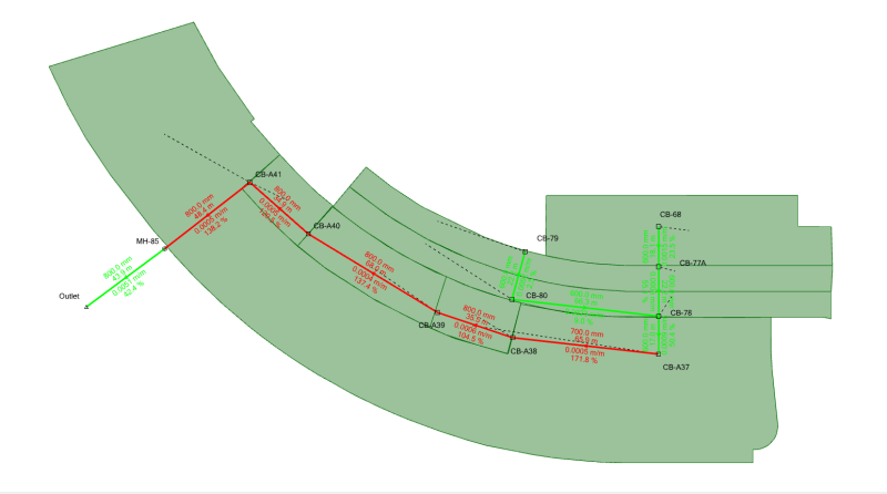
Now my problem is when I am analyzing an existing drainage system for post-development conditions and I get extra flow into the networks. See the pictures below for an example of a drainage system discharging into an empty open channel.
The plan shows that some of the pipes (highlighted in red) are undersized when analyzed for normal flow conditions with (%Flow/Pipe Capacity) ranging from 104.5%-171.8%.
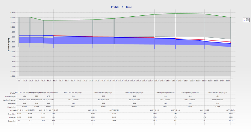
A look at the profiles on the other hand paints an entirely different picture as it shows the HGL below (or barely above) the crown of the undersized pipes. The explanation provided by Bentley is that the profile is drawn for Gradually Varied Flow conditions and because the pipe lengths are short, the flow will not achieve normal flow depth.

This makes me unsure on what judgement to make. Do I propose to replace the undersized pipes with larger capacity pipes, incurring extra costs? Or do I leave the system as it is since the GVF profile shows that the pipes won't be flowing full anyways?

plan_wyz01j.png

profile_jx7rg7.png
 
My bad on "modified rational" reference, I clearly got my terminology crossed up. Regardless, the explanation above covers how pipe flows are calculated in StormCAD. Instead of just summing the peak flows from the upstream pipes and catchments, it sums the "C*A" of the total upstream watershed of any given pipe, and then pulls a new "I" based on the total Tc, before calculating the flow in the pipe.

No municipalities I have encountered in Georgia or Florida allow storm drain designs for pressure flow anymore, after numerous design failures. Less sophisticated municipalities in Alabama and Mississippi often do. The problem with designing storm sewers for pressure flow is that the pipes themselves aren't really designed for it. If a contractor sets RCP within the appropriate tolerances, the joint is soil tight, but those tolerances are sometimes difficult to achieve in the field depending on bedding properties and such. And if there's a gap, and the pipe flows in pressure flow, it's going to wash the bedding away over time, creating sinkholes and promoting a failure.

It's not uncommon in my neck of the woods for a municipality to require the HGL stay inside the pipe for the 25 year, but allow the 100 year HGL out of the pipe as long as it's within the ground. So you show two HGLs on your profile.

As with all things Civil, regional standards vary, and are influenced by the experiences of the engineers within those regions.

Hydrology, Drainage Analysis, Flood Studies, and Complex Stormwater Litigation for Atlanta and the South East -
 
What's your design storm's return period Akel?

Hydrology, Drainage Analysis, Flood Studies, and Complex Stormwater Litigation for Atlanta and the South East -
 
It's a 10-Year design storm. The model is for a car parking area with a patchwork drainage system that the contractor is trying to redirect using existing and proposed pipes since the original outfall is no longer usable.
 
Akel - It seems that you need to determine if pressure flow is allowed or not for the design of this system. You can check your system by hand to see if STORMCAD is correctly calculating the losses and resulting HGL. We use a spreadsheet to verify systems that have odd results to confirm or in most cases identify incorrectly inputted data. I used my spreadsheet (slightly tweaked for HEC-22 access hole loss) before all the computer models became readily available. You just need to be comfortable with the results.
 
Run a 2 or 5 year and see what happens. If it's down in the pipe, then you're not pressurizing it very often and it might give you a level of professional comfort with the design.

Hydrology, Drainage Analysis, Flood Studies, and Complex Stormwater Litigation for Atlanta and the South East -
 
Status
Not open for further replies.

Part and Inventory Search

Sponsor