Basically I just need represent the assembly as shaded and not shaded with edges. I take the part in the assembly and make it invisible, but all the edge lines still show. I'm working on NX 12.
You might want to try changing the color of the edges so they show more faint.
You may also try looking into Render Sets, but I haven't worked with those so I can't tell you anything about them.
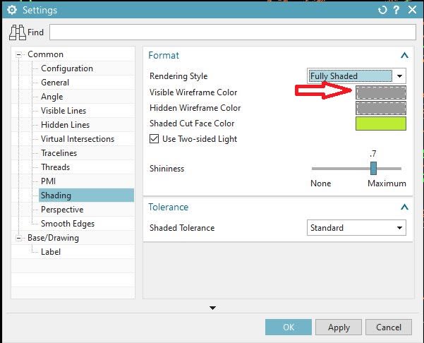
Go into the view Settings of the drawing view.
RMC on drawing view border -> Settings -> Shading
I am on NX1883, so it may look a little different than yours.
In my menu the greyish color is set because that symbolizes that the solid edge is the same color as the solid body.
Not sure why, but when I change that color I don't see any changes at all. Is there something else you do that special? I have the exact setting that you posted above.
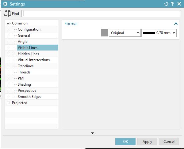
Maybe try changing the Visible Line color, six settings (on the left of the menu) above these shading settings.
I will check this when I get back to work tomorrow.
I opened up a drawing and shaded a view.
In my situation what I mentioned above did work, but what I am showing below worked too.
Below is showing the edges changed to grey,
Make sure you are exiting the menu properly by pressing OK.
I may have been unclear about something above.
To get to the view settings of a drawing view you need to RMC (right mouse click) on the border of the drawing view, then select Settings.
You can also get to the view setting by going into the model tree, expanding the drawing sheet,
then RMC on the view you want to change, and select Settings.
When you get into the view settings then make the changes I mentioned above.
This is very helpful. I tried everything and am still not getting any results. I feel like I have a setting I need to change in customer defaults to get this to work because I've tried everything and not getting what you are getting. I tried a new scratch part and drawings to the same result.
Do you know of any preference or default settings that may effect this? I'm going to seed through everything in the meantime.
I did find one more thing.
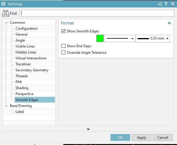
Make sure the color of the Smooth Edges is changed too.
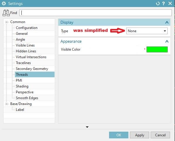
If you have threads it you may get a better result if you turn them off in a shaded view