Eng-Tips is the largest engineering community on the Internet

Intelligent Work Forums for Engineering Professionals

Side valve diesel engine 4

Status
Not open for further replies.

Redcobra2401

Automotive
Mar 25, 2024
11
0
0
US
thread71-400431 to further dive into alternative diesel engine designs, and I am by no means schooled in any areas regarding this just a general curiosity and Gained knowledge over the years.

The sleeve valve, side valve and one other "valve" type that is a rod with holes cut it that spins like a cam shaft has been tried.

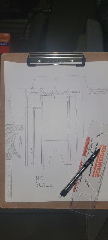
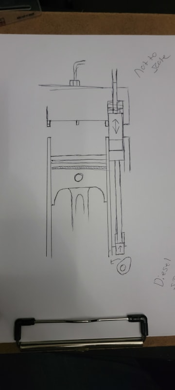
But how about this. an rod under spring pressure in a cylinder, parallel with the cylinder bore, that protrudes into the head. Corresponding Slots cut into the side of the cylinder and rod to allow for the flow of air and exhaust. See illustration

It would reduce the amount of waisted space minamizing the loss of pressure during the combustion stroke and still allowing for high compression required for deisels. simplify manufacturing with the possibility of no need for a "head" to the cylinders making it able to be casted as a single peice to be bolted to a crank case.

What ya think? Any potential worth diving deeper into? And pardon the art skills it was just the get the idea jotted down before it disapeared. And high I'm new here.
17113455474677570926125148845748_gyqmhr.jpg
 
Replies continue below

Recommended for you

Combustion chamber geometry is, above ALL OTHER THINGS, is the most critical part of diesel engine design. How is this side valve arrangement going to affect combustion chamber geometry?
 
When the piston is at the top of its stroke the piston would be past the ports for intake and exhaust. the voids are going to be responsible for some power loss as the piston comes down during the power stroke as the gas expands to fill them but it would be less voided space than a typical side valve. It would also keep the reliefs from being part of where the fuel is initially ignited ,and in my mind, reducing the potential for knock.

It would be simpler to manufacture with no need for a valve seat or valve reliefs to be cut into the cylinder head. The piston would be a standard diesel piston with the divit in the center for the fuel injection

I'm going to be drawing up a better picture in cad to easier illustrate this

Any and all info/critics is helpful I do hope to have this manufactured and attempt a running aircooled engine with the concept.
 
It seems simpler, which is the reason I would not hold much hope for it. A large number of people have been working on every possible configuration of engine valving for a very long time and if they haven't looked at this valve I would be definitely surprised.

A typical valve allows a large amount of flow with a small amount of movement, seals in spite of small amounts of wear, is reasonably insensitive dimensional changes, and evenly distributes the loads onto the valve seat.

Slide valves have been used in the past, but were abandoned for most engines. See
 
With the introduction of Nitronic and Nimonic alloys most, valve wear is nearly eliminated and they can be run directly in the head castings without guide or seat inserts except in the case of aluminum.
 
I get that there is new technology that makes this an obsolete idea, im not claiming its the next best thing. The general hopes with this idea is to further simplify the already simple machining that side valve engines are known for and make the disadvantages of the low compression nature and bad geometry of side valves engines less apparent. I think it has hope I've just gotta think it out some more and draw up better images

I'll be back in a few days with a cad design for this. And I appreciate your thoughts.

 
To further Tug's point ... The shape of the combustion chamber - nowadays, the recess in the piston - is closely tied to the spray patterns and reach of each orifice in the injector nozzle, and the directions of airflow in the chamber as the piston approaches top-dead-centre so as to maximise air and fuel mixing. The air has to be where the fuel is sprayed to, and the air has to be moving as it passes the injector stream so that as the spray breaks up, it mixes with the air flowing in the chamber as quickly as possible.

In order to make this happen optimally, "dead volume" (air volume without direct exposure to fuel sprays) has to be at an absolute minimum. With a normal modern (flat) cylinder head, clearance pockets for the valves are as minimal as possible so that as much of the compressed volume as possible is in the piston recess (which is where the injector spray pattern is) and as little compressed volume is in the outer reaches of the cylinder outside the perimeter of the recess in the piston.

I see no way you can get enough flow area without introducing excessive dead volumes that injector spray patterns can't get directly into.
 
Taking all your points into perspective I came up with a new idea "sparing the rod" .. well part of it any way.

Hopefully this is a solution to Brian's points and this is just trying to get a viable base to improve upon in a final design.

In keeping with the theme of it being simple to manufacture I give you this, using similar slots in the cylinder as would be in an old Detroit.

17115028381676260241793665309818_vzjggp.jpg
 
The "slots" are coming back. Achates Power is developing a modern opposed piston engine that is fully ported. The OP design has some emissions and efficiency related benefits due to double the expansion rate. However, do note that the Detroit style slots are all of the way around the lower cylinder and angled to promote swirl.

And before anybody calls the Detroit 2-strokes dirty, I built two of them that met US EPA Tier 2 emissions standards without electronic controls.
 
So basically a sleeve valve. Calculate the dead volume of the ports (thickness of cylinder liner x total area of ports). Bearing in mind that with these ports being near the top of the piston stroke, the top compression ring has to be well below the top of the piston so as to not pass over the port area, calculate the dead volume associated with the piston clearance to the cylinder wall factoring in the excessive distance that the top compression ring has to be below the deck. Modern engines have been moving the top compression ring as high up the side of the piston that they can get away with and still have ring-lands that are strong enough, in order to minimise that dead volume ...

And there's another thing to consider: Leakage. Sleeve valves, as with anything else, require clearances between moving parts in order for those moving parts to keep moving and not seize against each other. Compounding this, you are dealing with compression and combustion space, and hot exhaust gases. How much clearance between the moving parts? How much flow (leakage) area does that clearance lead to? How's that going to work with 18:1 compression ratio? And how are you going to lubricate that?

Sleeve valves have been tried. They ain't used any more. There's reasons why they were tried and found wanting.

Poppet valves have some pretty amazing features. When closed, they are in actual physical contact with the surface that they are expected to seal against, but they never actually have to slide against that surface. Cylinder pressure acts to further tighten up that seal. Thermal expansion of the valve simply leads to the valve closing a wee smidge further out into the chamber and doesn't impair its ability to seal and doesn't make the mechanism seize. The parts of the mechanism that do need to slide relative to each other - the stem inside the guide! - are outside the compression space, so a wee bit of leakage in that area does not have catastrophic consequences.

Leaky poppet valves due to carbon build-up or excessive valve-seat wear etc leads to an engine that won't start, due to compression loss. Sleeve valves or rotary valves or spool valves or any other type of valve that requires relative motion at a surface that is expected to be sealed, all require clearances due to those relative motions, and they will all LEAK!

Poppet valves in an overhead-valve configuration are going to be with us until the end of internal combustion engines ...
 
The diff with the Detroit Diesel design is that the ports were all down near the bottom of the piston stroke, not exposed to compression pressure, so it didn't matter if there was a bit of dead volume and it didn't matter that the piston rings crossed the ports, because it didn't matter if there was leakage past the compression rings when there was next to no compression pressure in effect at the time that the rings crossed the ports. The exhaust valves, in the cylinder head and therefore exposed to combustion pressure, were poppet valves.
 
So am I on the right track tugboat?

The end goal is to have the slots cover between 1/2 and 6/8ths of the cylinder circumference divided between exhaust and intake. if I can get the "valve" designed right to allow for it. I want it to be 4 stroke eliminating the need for a supercharger (both achates power and detroit need them) and it will be air cooled.

If lucky, good enough to be used in some tractors or generators.
 
Tractors and generators are both under emissions compliance rules. You WILL NOT be able to sell this engine if it doesn't meet the current emissions standards. How do you think your design is going to improve emissions?

Heck, here in California they are telling me I am not even allowed to run my compliant engines.

The 2-stroke engine has benefits from an emissions and efficiency standpoint hence the renewed interest.
 
It would have to be a tight clearance ... maybe allow it to not necessarily seize in place but get barley stuck on closing and use timed hydraulic pressure to dislodge it? Tapering the sleeve pocket and making clearances to insure the sticking only happens at operating temp and only on the valve closing.

Haven't got far enough to figure out lubrication yet but I'm hoping to get there.

And the drawing is just a principal not what it would actually look like so I could move the ports up and angle the sleeves, instead of them being parallel to the cylinder, to have the ports in the top corners of the cylinder raising the compression ring on the piston and maybe being able to put dimples on the piston to fill those voids as much as possible. I don't think complete elimination of the space is possible but i think I could get it to almost nothing doing that.

So a few more components to the valve train but keeping the cylinder simple still.


You don't want lubrication, that causes particulate matter emissions. You need to identify material pairings that can operate without additional lubricants.

Keep in mind that the big players, Cummins and Volkswagen are struggling to meet requirements and have been caught cheating emissions standards. Emissions are the most absolutely critical aspect of design for a diesel engine today.

How does your design reduce emissions? If it doesn't reduce emissions then don't bother moving forwards with it.
 
I guess I need to say this I'm not going to sell this design the market is already dominated it would be near impossible and I'm starting it with a failed concept, I get that I'm not in denial lol.

I just want to simply design and if I'm lucky make a one off aircooled diesel engine that isn't conventional but fuctions well enough to power some type of equipment and doesn't care about emissions laws cause metal can't read.

Just starting off with the standard subborn project C.D.M.
Can it work?
Does it work?
Make it work.
 
Well, if you can make 300-400 psi compression while cranking it will diesel. I suggest researching Nitronic alloys for your valve mechanism if you want it to have any kind of longevity.
 
You guys are helpful tho I've already learned a good bit, being a truck driver with a million ideas and unusable time on his hands this is a project I can start without needing a shop and fill those hours of waiting in a dock.

Any good reading material yall recommend to find out how much certain metal alloys expand with heat? And what alloys are typically used in engines?
 
Status
Not open for further replies.
Back
Top