Continue to Site

Eng-Tips is the largest engineering community on the Internet

Intelligent Work Forums for Engineering Professionals

  • Congratulations KootK on being selected by the Eng-Tips community for having the most helpful posts in the forums last week. Way to Go!

Sign convention of CBUSH forces 2

Status
Not open for further replies.

Zadrobu

Structural
Sep 7, 2014
38
I have obtained the forces of a set of CBUSH elements with the ELFORCE output command. What I'm now wondering about: what exactly determines whether a force component is positive or negative?

I have the feeling that the answer will be quite trivial, but thus far I haven't been able to fully figure it out yet. If anyone could provide some insight I'd very grateful!
 
Replies continue below

Recommended for you

Hi Zadrobu, I would assume the coordinate system defined for the element should help you understand the sign convension. Do a test by changing your CBUSH coordinate orientation and check the kind of signs you get for the forces ()X-axis along the CBUSH elm)
 
Thanks for the reply. I had not mentioned this yet, but I'm generating all my force outputs for the global coordinate system 0. The problem was that I didn't understood at which location the force was evaluated and whether it was an action or a reaction force (all of which should affect the sign). I have done some tests like you suggested however. It seems to me now that the ELFORCE output from CBUSHes is always equivalent to the force that the CBUSH exerts on the first grid defined in the CBUSH card. Anything definitive regarding all this I have not been able to find in any of the Nastran manuals.
 
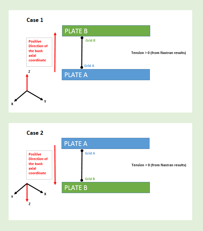
Checked the document too, but still it tries giving a couple of "what if" examples. I found this error when I started working on Airbus A350xwb Wing Ribs, and it turned out some of the fastener tension/compression loads had wrong directions. I want to summarize as follows:
Rule 1) The direction of the coordinate axis should align with the direction from "Grid A to Grid B" of the bush element.
Rule 2) The "positive" direction of your coordinate system (for tension/compression direction - also known as: fastener axial coordinate) should "first meet" the plate which belongs to Grid A.

In the below snapshot, I also added the vice-versa cases. This should cover everything. You may also add RBE2/RBAR elements to the Grids in case you have geometrical offset between your bush and plate nodes.

CBUSH_zz782v.png
 
Status
Not open for further replies.

Part and Inventory Search

Sponsor