Continue to Site

Eng-Tips is the largest engineering community on the Internet

Intelligent Work Forums for Engineering Professionals

  • Congratulations KootK on being selected by the Eng-Tips community for having the most helpful posts in the forums last week. Way to Go!

Sign Convention !

Status
Not open for further replies.

Hudhaifa

Structural
Apr 9, 2018
21
Hi all
As a matter of interest to learn how to design a reinforced concrete buildings, I have started reading a book named "Reinforced Concrete Design (7th edition) to EuroCode 2, by Mosley ... "

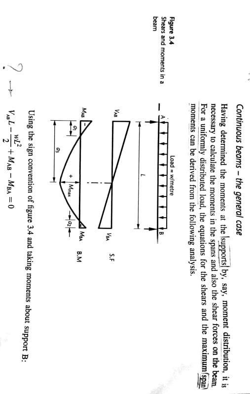
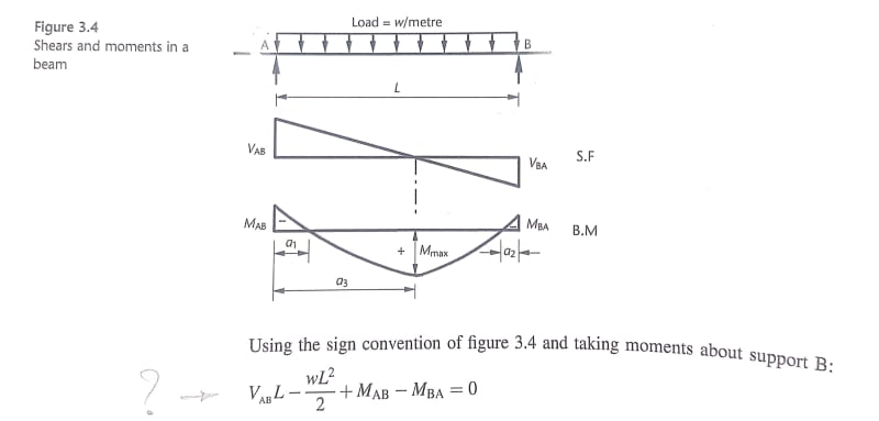
My questions may seem to be obvious and easy, but it really confused me. While I am reading Analysis Section, the book considers the following sign convention;

New_Doc_2019-05-21_10.41.24_1_qsbple.jpg


the question is how the equation shown in the photo below has been found ? I mean the signs of all actions (loads) and Moments.
New_Doc_2019-05-21_10.41.24_2_l6iju8.jpg


Should not the book show the direction of M(AB) and M(BA) in the free body diagram to expect the sign of them ?

Hope find anyone who could explain to me.

Thank you
 
Replies continue below

Recommended for you

It's commonly known that the European orientation of moments is different from that of say the Americans. This is evident in many software suites (SAP2000 for example) where there is an option to reverse the moment display according to regional preferences. I think it would be preferable not to get your basic structural analysis knowledge from a textbook on concrete design. Read a structural analysis/solid mechanics book on beam theory. Once your analytics are there, then move to design.

Your moment diagram will follow the basic deflected shape of the beam, the non-Euro book would be opposite. The bottom line for the design stays the same, so don't let it hinder your learning.
 
the moment plot follows the sign convention quoted (somewhere else in the book ?). The down distributed load will cause the beam to sag (hence +ve moment mid-span) Fixed supports tend to oppose the beam moments (hence -ve).

the equation looks to be sum moments about end B (as stated), CW moments +ve. The possible ambiguity is whether the moment terms are signed or absolute values.

The reaction moments are … Ma is CCW and Mb is CW, to react the applied loads/deflections. So … I guess I'd change the moment terms sign … but …

another day in paradise, or is paradise one day closer ?
 
DrZoidberWoop said:
It's commonly known that the European orientation of moments is different from that of say the Americans. This is evident in many software suites (SAP2000 for example) where there is an option to reverse the moment display according to regional preferences. I think it would be preferable not to get your basic structural analysis knowledge from a textbook on concrete design. Read a structural analysis/solid mechanics book on beam theory. Once your analytics are there, then move to design.

Your moment diagram will follow the basic deflected shape of the beam, the non-Euro book would be opposite. The bottom line for the design stays the same, so don't let it hinder your learning.

Yes exactly. that what I notice the moment orientation is different from European to Americans. For Example in american book CW FEM
consider as positive and CCW FEM as negative which is opposite to European.

This is one of the reason that confused me as the structural analysis book that we used in university "Structural Analysis 7th edition, by Hibbeler" is an american book, where the book I am using for concrete design is European book as we here follow British Standard in Design.
 
hinder said:
the moment plot follows the sign convention quoted (somewhere else in the book ?). The down distributed load will cause the beam to sag (hence +ve moment mid-span) Fixed supports tend to oppose the beam moments (hence -ve).

the equation looks to be sum moments about end B (as stated), CW moments +ve. The possible ambiguity is whether the moment terms are signed or absolute values.

The reaction moments are … Ma is CCW and Mb is CW, to react the applied loads/deflections. So … I guess I'd change the moment terms sign … but …

if we follow the sign convention in point 1 as shown in the photo below

image_mcw6pl.png


the signs of M(AB) and M(BA) shown in the equation is correct if we consider M(AB) as CW and M(BA) as CCW.
However what about the remaining loads; uniform load and V(AB)?

I am wondering why the direction of moments M(AB) and M(BA) are not shown in the free body diagram? it would be easier for the reader to follow-up the author idea.
 
Ma is definitely CCW, opposing the deflection of the beam. So sum moments about B would be …
Va*L-1/2*w*L^2 -Ma+Mb = 0 … with the moments drawn the way I assume them to be, but these directions cause hogging so by the sign convention …
Va*L-1/2*w*L^2 +Ma-Mb = 0 … given that moments are +ve in a "sagging" sense (ie CW at A, CCW at B)

another day in paradise, or is paradise one day closer ?
 
You can choose any sign convention you want, just be consistent.
 
yes, it's just that in this case it is IMO not so straight forward. It would be clarified if they had end moments shown (like they show the shear reactions)).

another day in paradise, or is paradise one day closer ?
 
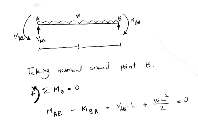
Following the above mentioned sign convention to get +ve M(AB) and -ve M(BA) as shown in the book ... I consider the assumption below;

New_Doc_2019-05-22_00.02.06_1_uwfxd5.jpg


But the sign of loads Vab and w are opposite to what shown in the book itself.
 
no, Ma and Mb are their real directions, BUT they are hogging the beam. Therefore +ve Ma and Mb are opposite, and so the sign work out. The result will be -ve moments (which are moments in the directions you show.

another day in paradise, or is paradise one day closer ?
 
Everything is an absolute value. The directions are taken care of by the pluses and minuses so you have to know that the end moments are both hogging to get these right. This leaves me wondering what you're solving for since some analysis has been done before this stage to determine that the moments are hogging.
 
in his last sketch he drew the moments as they will be (to react the down distributed load). But these are not the +ve convention (that his book used to come up with their equation).

I assumed the same directions and came up with a different moment equation and then figured out the difference so I could get the same equation with some logical reasoning.

The point to my last sentence (in my previous post) was much like your post … the moment is acting in a particular direction … +ve in one sign convention, -ve in the other.

another day in paradise, or is paradise one day closer ?
 
rb1957 said:
in his last sketch he drew the moments as they will be (to react the down distributed load). But these are not the +ve convention (that his book used to come up with their equation).

I assumed the same directions and came up with a different moment equation and then figured out the difference so I could get the same equation with some logical reasoning.

The point to my last sentence (in my previous post) was much like your post … the moment is acting in a particular direction … +ve in one sign convention, -ve in the other.


So we can say the direction of Ma and Mb shown in my last sketch are correct. BUT still the signs of Va and w in my equation is different to the one shown in the book I use.

In general, I used to consider different sign convention by other book for analysis, which is different to the one considered in this design book. But I raised this question to know exactly how this equation found.
 
I see, I got the moments the wrong way around. Let's see if I do better this time...

I think the sign convention used is:
V is positive upwards.
M is positive sagging.
W is positive downwards, sometimes adopted as most loads are due to gravity.

 
"So we can say the direction of Ma and Mb shown in my last sketch are correct. BUT still the signs of Va and w in my equation is different to the one shown in the book I use." instead of "BUT" I'd've said "AND" … your sketched moments are not the +ve sign convention of the book (you can see that, yes?). If you show them in their +ve directions (sagging the beam) then all will become right.

"In general, I used to consider different sign convention by other book for analysis, which is different to the one considered in this design book. But I raised this question to know exactly how this equation found."
If you Know your positive sign convention then you can work with it. If you can understand a different sign convention (like in this book) then you should be able to show that the answer does not depend on the +ve sign convention (only the sign of the moment will change as you change which way is +ve).

another day in paradise, or is paradise one day closer ?
 
Don't know if this helps to visualise things/cement things in people's minds, but the moment is drawn on the tension side of the member typically (at least in these parts). I didn't know there was any other way, it would seem counter intuitive to think about it any other way.

I got the feeling it's part of a continuous Beam, that's why no moment reactions are shown, moment is an internal force at the ends of this segment.
 
re-read yr post from 21:12 …

yes, I agree. They've shown w positive down, and the shear reactions +ve up … both pretty standard conventions.

They're being "pedantic" about the "+ve moments cause sagging" convention 'cause in the general case (of moment distribution along a multi-span beam) it is difficult to see which way the moments would be so apply one convention consistently. Had they used "+ve moments cause hogging" this would have been more consistent with their force convention but … meh!

another day in paradise, or is paradise one day closer ?
 
Agent666 said:
I got the feeling it's part of a continuous Beam, that's why no moment reactions are shown, moment is an internal force at the ends of this segment

Yes it is a part of continuous beam. But even though shouldnt moment direction to be shown ?

See the image below
New_Doc_2019-05-23_00.36.48_1_cavtmh.jpg
 
ok, now we're circled back to the original post. The equation is correct as written 'cause of the +ve sign convention they've used.

They could easily have draw their +ve convention (sagging moments) on the BM diagram, where the -ve value shows the end moments to be hogging (as we'd expect).

another day in paradise, or is paradise one day closer ?
 
Yes, now you're just getting into preference. They could have shown curving arrows on a diagram to show moment sign convention, but they instead chose to do it by text (item 2 from your original post).

Agent666, the shear force is also an internal force, but is nonetheless shown on the diagram? The external reaction will be the sum of the shear forces from the two adjacent spans.

(So glad this thread hasn't wandered into shear force sign convention. Does my head in.)
 
Status
Not open for further replies.

Part and Inventory Search

Sponsor